Photoelectric tracking adjustment
ü Photoelectric Eye Mark Tracking---Step1-6
ü Blister Forming Centering---Step 7
ü Cutting Position Centering--- Step 8
ü Cover Film Centering---Step 9
ü Film Replacement Precautions
This is the second part of the article,Click me to enter the first part of the article---->>>>.
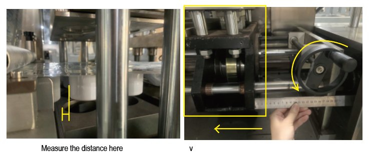
Turn the knob counterclockwise to move the forming mold to the left direction by the (previously measured) distance.
Note1: When adjusting the position of the blister, please make sure that the cover film is also put on the machine and participates in the adjustment together with the forming film.
Because the cover film has tension, it will drive the forming film to move forward due to the interacting forces between them.
Putting the forming film to adjust the forming position first, and then putting the cover film after adjustment will cause blisters to be squashed again and the forming position still needs to be adjusted again.
This wrong operation will waste time and material.
Note2: Each time after turning the knob, it is necessary to confirm the blister state after adjustment after the first version (that is formed after adjustment) to reach the cutting position.
Step 8
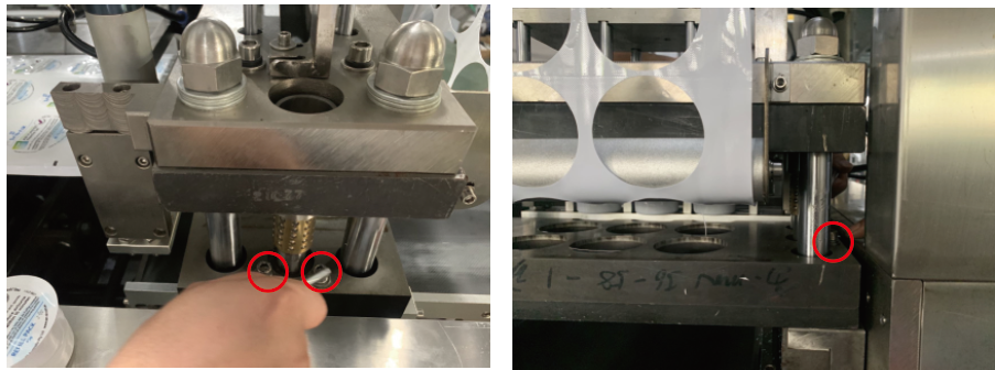
After the forming position is adjusted well, run the machine and check whether the position of the blister cutting mold is centered.
If the cutting is not correct as the below picture shows.
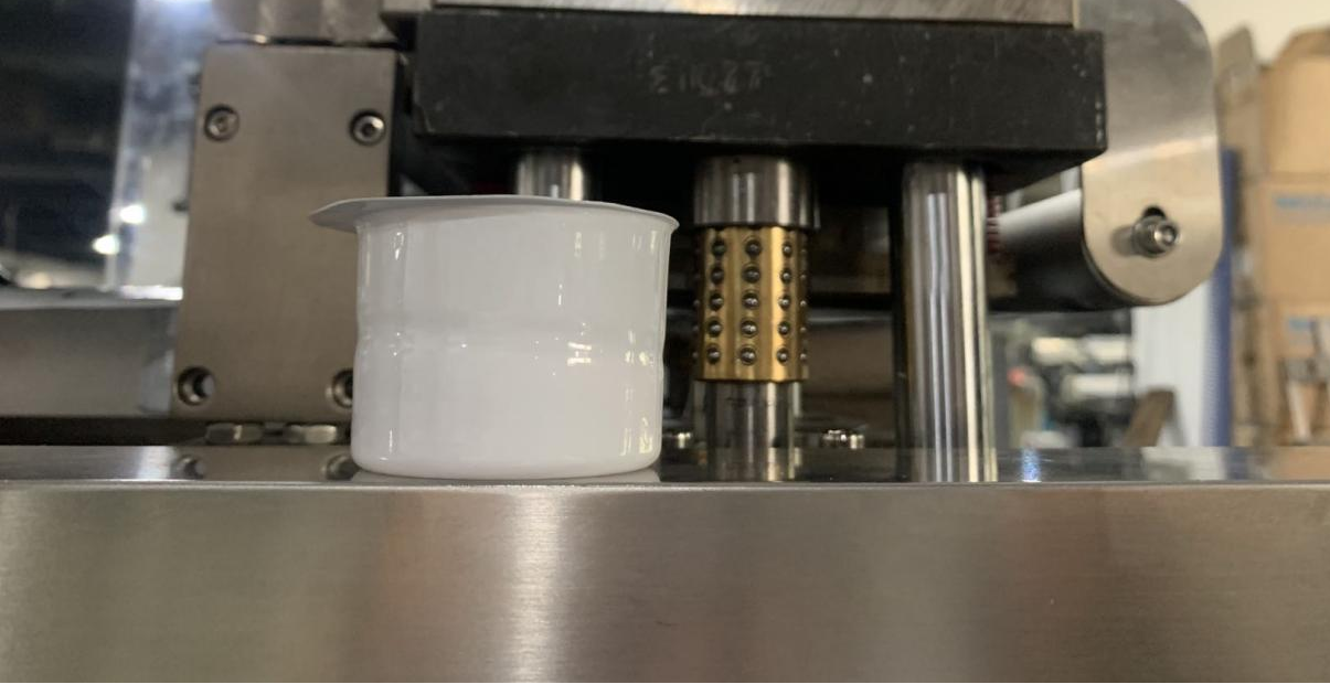
The cutting position needs to be adjusted in the left and right directions.
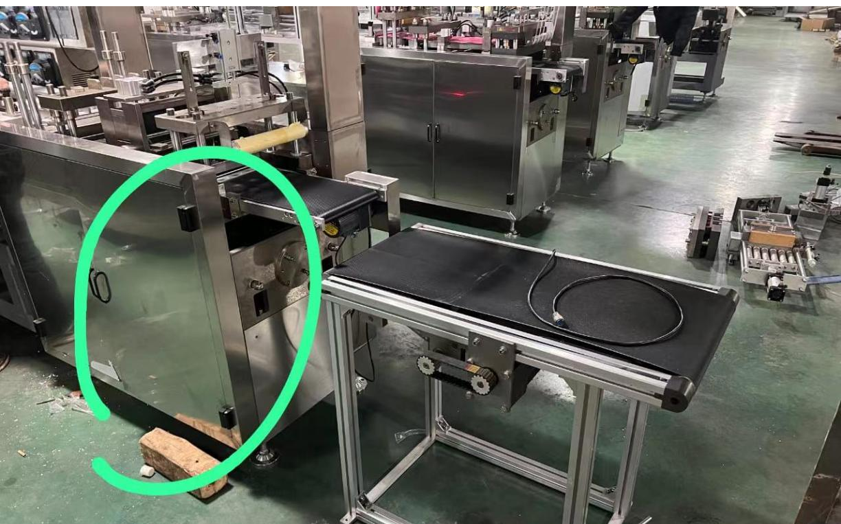
Pls open this door (in the green circle), there are two knobs.
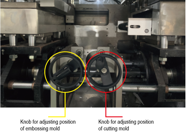
The left knob is for adjusting the position of embossing.
The right knob is for adjusting the position of cutting.
Before turning the knob, pls separate the mold first, otherwise it cannot be turned.
How to separate the mold?
Click and turn off “bubble, traction, forming tensile" (to red color) on the touch screen, and press the jog button to run the machine and let the heat-sealing mold go to the lowest.
To adjust the cutting position in inside and outside directions, loosen the 10 screws (shown below) to move the mold inwards and outwards.
Pls judge according to the actual situation of the cutting position, and move to a proper position.)
|
4 screws |
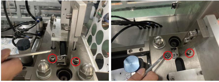
|
4 screws |
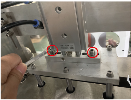
| 2 screws |
Remember to tighten these screws after adjustment.
Step 9
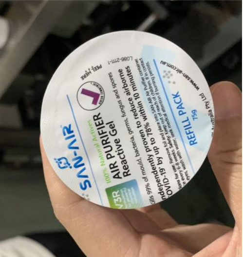
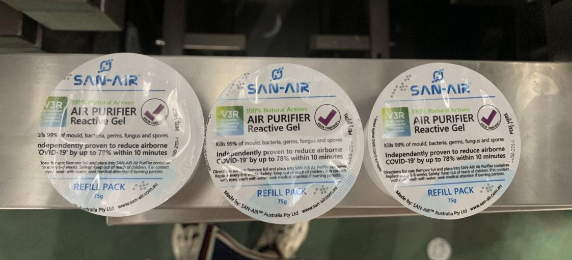
After the forming position and the cutting position are adjusted well, run the machine and check if the cover film is centered when there is bubble being formed.
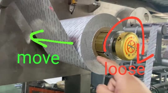
If the position of the cover film is very different, for example, as shown in the picture, we need to move the cover film by a large distance towards the arrow direction.
Pls loosen the knob in the picture below and move the cover film to the proper position.
If the difference is very slight, as the below picture shows, i.e., there is a small deviation in the direction of the red arrow.
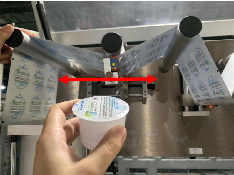
Moving the cover film roll directly is not a good choice.
You can adjust as below:
Turn the screw here to move the cover film and the sensor to the left or to the right to the appropriate position according to the actual situation.
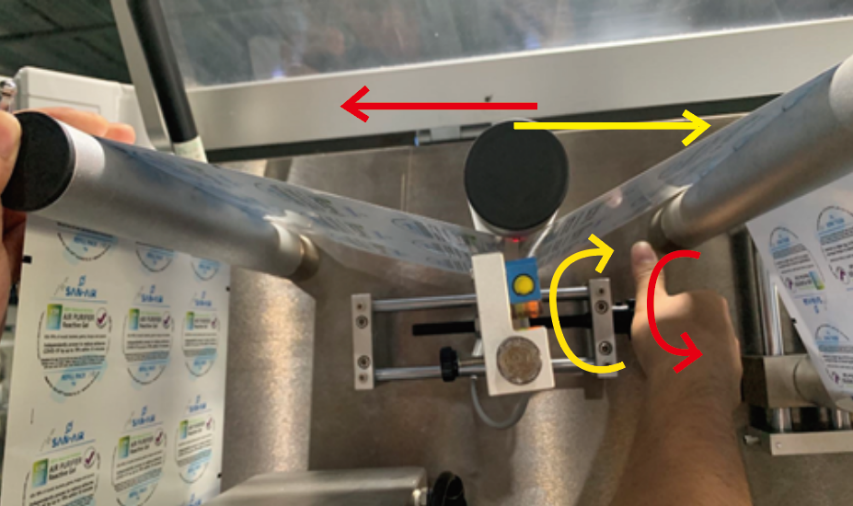
| Turn it outsides, and the cover film position moves to the left.
Turn inwards, and the cover film position moves to the right.
|
If the difference is very slight, as the below picture shows, i.e., there is a small deviation in the direction of the yellow arrow.

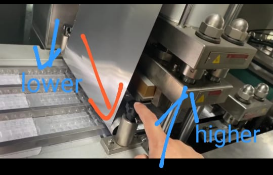
Turn the knob with the outside being higher and the inside being lower, and the cover film will move to the outside.
| 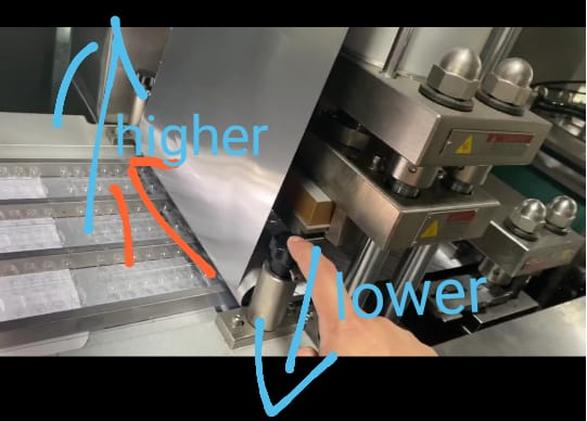
On the contrary, if the outside one is lower and the inside one is higher, the cover film will move to the inward.
|
Note that the photoelectric position needs to be finely adjusted according to the position of the cover film.
| Turn the screw here (on the left side of the photoelectric sensor) to adjust the front and rear position of the photoelectric sensor.
|
Through the above method, the position of the cover film will be adjusted to a good position.
When the material is used up and the film needs to be replaced,
pls note that:
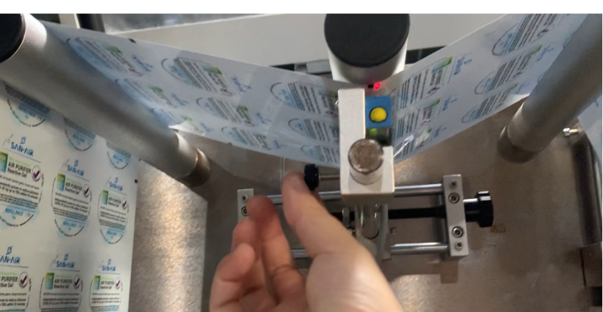
Cover Film Replacement
Pls make a mark on the cover film cylinder with a pen (or measure the size from the edge with a ruler) to make sure that the position of the cover film is at the same place every time
(when replacing the cover film).
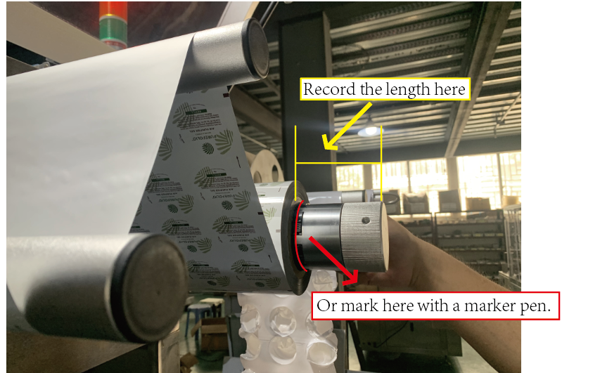
However, when replacing the cover film, the position will inevitably be a little bit deviated, and then the position of the cover film should be fine-tuned later (check step 9)
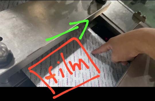
Forming Film Replacement
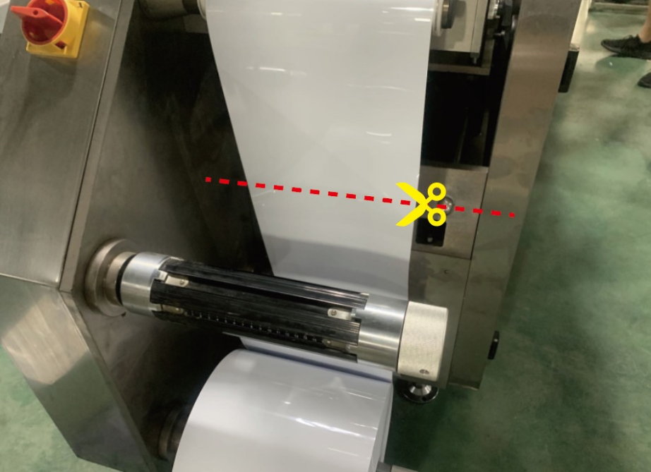
After cutting it here, pls put the new film on the roll, stick it with tape, and then run the machine.
This is the second part of the article,Click me to enter the first part of the article---->>>>.

 English


