Photoelectric tracking adjustment
ü Photoelectric Eye Mark Tracking---Step1-6
ü Blister Forming Centering---Step 7
ü Cutting Position Centering--- Step 8
ü Cover Film Centering---Step 9
ü Film Replacement Precautions
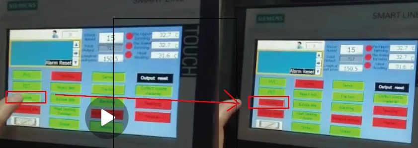
Step 1 Stop bubble forming and change fixed length to fixed mark.
1) Press the bubble button to red color, to stop bubble blowing.
Very important! Align the color mark in the situation of no bubble. (Without blister forming)
It will be not correct, and not accurate to align color mark in the bubble situation.
2)Press the fixed length button and change it to the fixed mark.
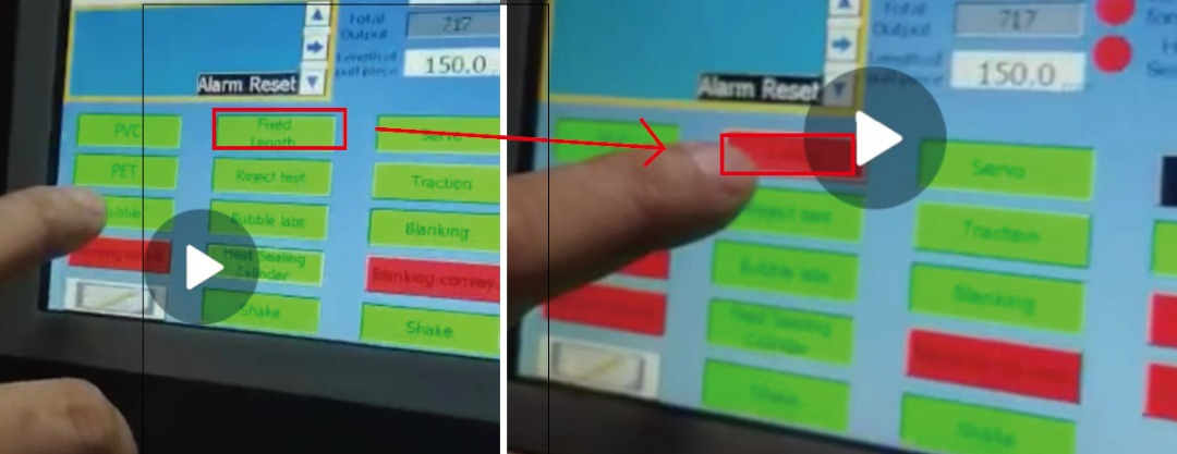
Very important! pls keep it at the fixed mark, not the fixed length, because we need to align the color mark.
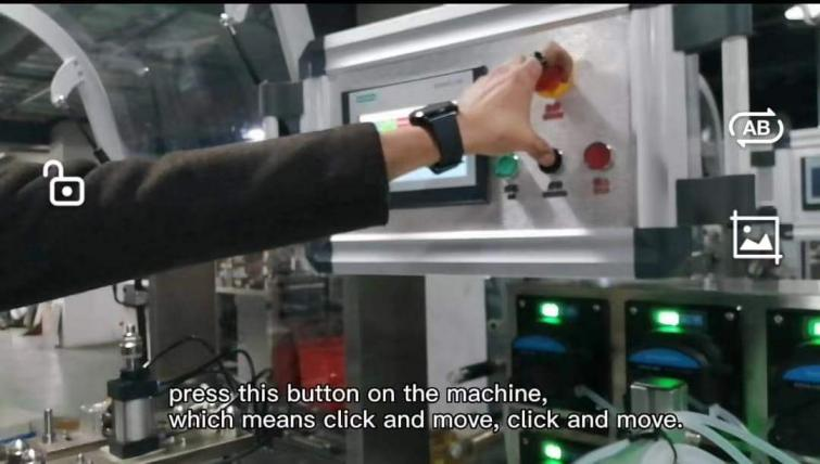
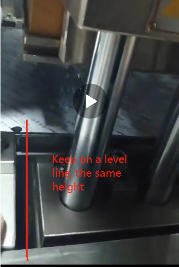
Step 2 Adjust the heat sealing mold to its top and to be level with the table.
Press the jog button and run the machine, to let the heat-sealing mold be lifted to the highest, and on a level line with the machine table (the same height as the machine table)
(Kind tips: there is a jog button beside the touch screen, the machine will run once the button is pressed, but stop running when you release your finger. This button is usually used in adjustment)
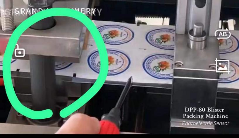
Step 3 Pull the cover film to the accurate position and align the black spots with the heat sealing mold.
Please pull the cover film to the correct place, and ensure that the cover film is in the correct sealing place, as shown below (in the green circle). The two black dots are aligned with the heat sealing mold.
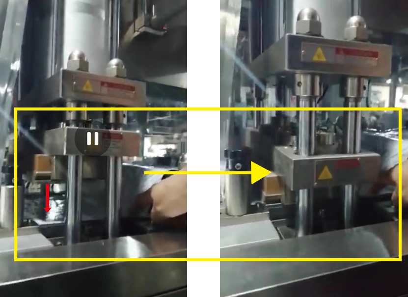
Step 4 Lower the heat sealing cylinder to make it hold down the cover film.
Press the ‘heat sealing cylinder” and let the heat sealing cylinder go down to hold down the cover film so that the film cannot move.
Step 5
Adjust the photoelectric sensor, and align the photoelectric sensor's light spot with the cover film's black dot.
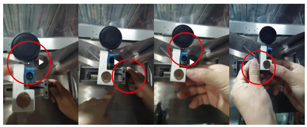
1. Check here, and find that the light spot is not aligned with the black dot. | 2. Turn the screw here (in the red circle) to adjust the left and right position of the sensor. | 3. After adjustment, we find the front and rear position of the light spot of the sensor is not aligned with the black spot. | 4. Turn the screw here (on the left side of the photoelectric sensor) to adjust the front and rear position of the sensor. |
Pay attention to letting the light spot of the sensor be closest to the black spot. It is best to align it vertically and not skew. |
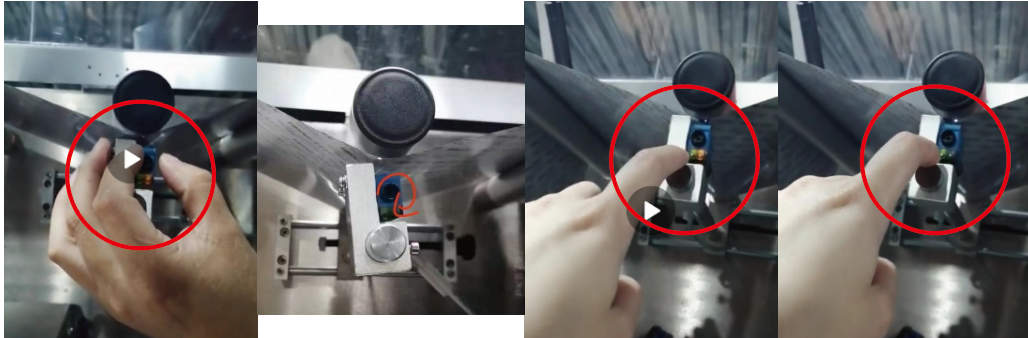
5. Twist the knob until the two lights appear. There are two lights under the knob, a red/orange light, and a yellow/green light. | 6. When the light spot of the photoelectric sensor is aligned with the black dot, both lights will light up. | 7. Pull the cover film, move the black spot, and check whether the light of the photoelectric sensor changes. |
Correct situation: when the light spot is not aligned with the black dot, the orange/red light will be off, and the orange/red light will light up when they are aligned.
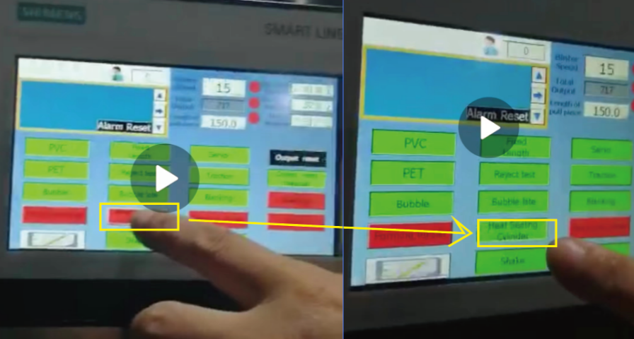
Step 6
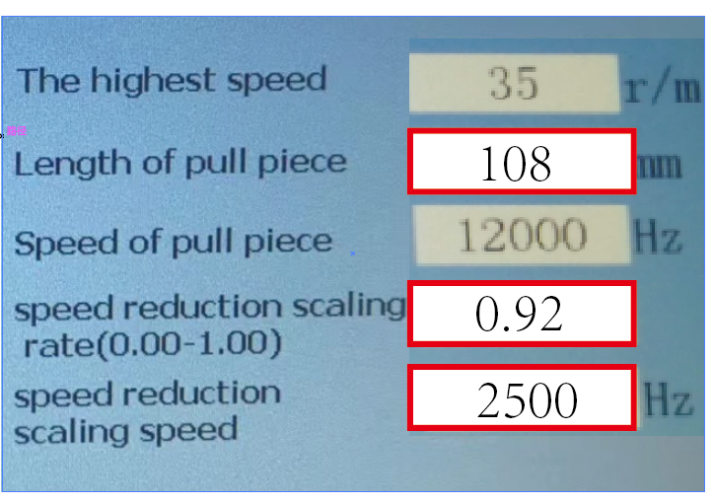
Measure the distance between the two black dots and then set the “length of pull piece”(on the touch screen), generally 4mm larger than the distance between the black dots.
For example, if the distance between the two black dots is 104mm, then the “length of pull piece” can be set at 108mm.
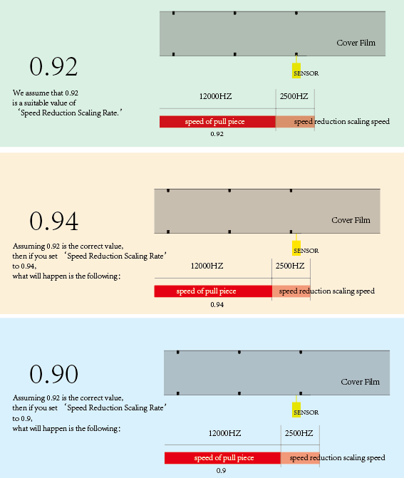
The “Speed Reduction Scaling Rate” is generally set to 0.92 first.
(Later will be adjusted according to the actual situation.)
“Speed Reduction Scaling Speed” is generally set to 2500Hz, it can be increased to 4500Hz, depending on the running speed of the machine.
After setting, run the machine without blister forming to check if the photoelectric sensor always catches the black dot accurately.
IMPORTANT: When running the machine, pls stop bubble forming, and choose the fixed mark.
If the photoelectric sensor does not catch the black dot accurately, pls check the position the light spot of the photoelectric sensor directs to. Is it on the left of the black dot, or on the right of the black dot? And how far is it from the black dot.
There are two methods to adjust.
Method 1(The recommended method)
Change the setting value of ’Speed Reduction Scaling Rate’ on the setting screen, according to the positional relationship between the light spot (of the sensor) and the black dot.
l Reduce the "Speed Reduction Scaling Rate" value, and the black dot will move to the right.
l Increase the "Speed Reduction Scaling Rate" value, and the black dot will move to the left.
l The value should be adjusted from small to large.
Repeat adjustment in this way until the photoelectric sensor can always catch the black dot when the machine runs. (The light spot can always align with the black dot.)
Then this step is successfully finished.
The figure below shows the principle of ‘Speed Reduction Scaling Rate’ to help understand.
Method 2
Change the setting value of “length of the pull piece” on the setting screen, according to the positional relationship between the light spot (of the sensor) and the black dot.
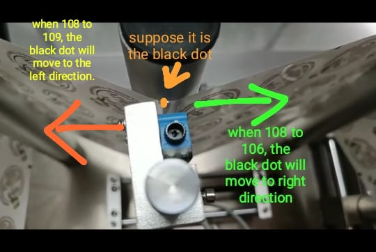
If the light spot (of the sensor) is on the right side of the black dot, change the setting value of “length of pull piece” to a smaller value. The greater the value change is, the greater the distance the black dot moves by.
For example, if the original value is 108, we can change it to 106 or 107.5, there can be a decimal point, and it can be adjusted by 0.1mm.
Conversely, if the light spot (of the sensor) is on the left side of the black dot, change the setting value of “length of pull piece” to a larger value.
Repeat adjustment in this way until the photoelectric sensor can always catch the black dot when the machine runs. (The light spot can always align with the black dot.)
Then this step is successfully finished.
Note1:
Only need to adjust the parameters on the screen to move the position of the black dot. Do not adjust the sensor position by hand.
Note 2
When adjusting, NOTE that when the black dots and the light spot do not align, after adjusting the value on the touch screen, pls pull the film to manually make the black dot align with the sensor, and then start the machine to let the photoelectric sensor find the black dots automatically.
(When pulling the film, turn off the “traction” on the touch screen)
Note 3
When changing the speed of the machine, the “speed of pull piece” needs to be changed too.
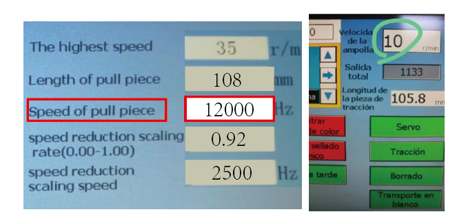
The following table is for your information
Machine Speed | Speed of pull piece |
10-11 r/min | 12000Hz |
12 r/min | 13000Hz |
13 r/min | 14000Hz |
14 r/min | 15000Hz |
15 r/min | 16000Hz |
16 r/min | 17000Hz |
17 r/min | 18000Hz |
18 r/min | 19000Hz |
19 r/min | 20000Hz |
20 r/min | 21000Hz |
and so on.
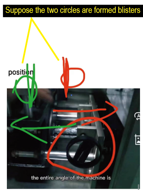
Step 7
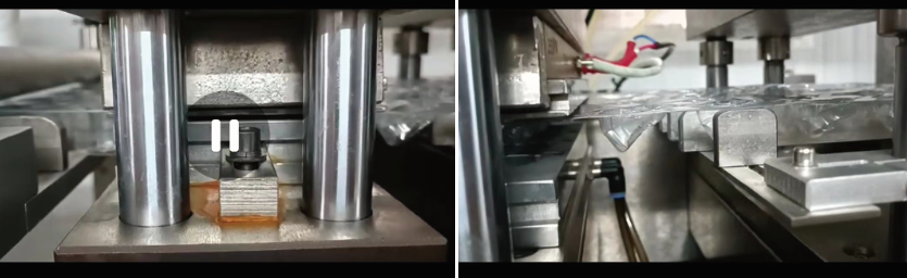
Click the bubble button (on the touch screen) to green color, and run the machine with blister forming. Check whether the heat-sealing mold fits well with the blister, and the blister will not be squashed.
If they don’t match well, blisters will be squashed as the following picture shows.
Then, we need to adjust the forming position.
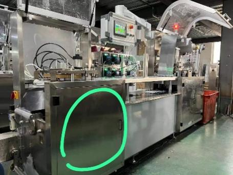
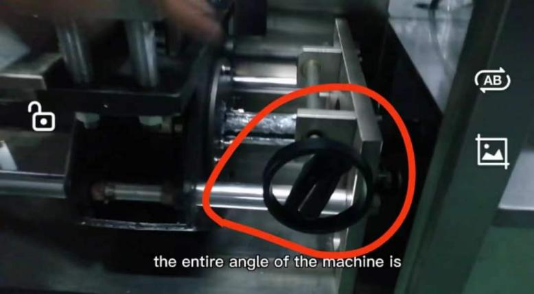
Open the door (in the green circle in the left picture), and there is a big knob (in the red circle in the right picture), turn it to adjust.
When turning the knob, pls separate the mold first, otherwise it cannot be turned.
How to separate the mold?
Click and turn off "bubble, traction, forming tensile" (to red color) on the touch screen,
And press the jog button to run the machine, to let the heat-sealing mold go to the lowest.
(Kind tips: there is a jog button beside the touch screen, the machine will run once the button is pressed, but stop running when you release your finger. This button is usually used in adjustment)
(Pls check in the step 2 by which the mold can be lifted to the highest position.
If you want to separate the mold, please run the machine and let the mold to the lowest position.)
| If the blister is squashed on the left part as indicated by the red circle, turn the knob to the right (red direction) |
If the blister is squashed on the right part as indicated by the green circle, turn the knob to the left (green direction) |
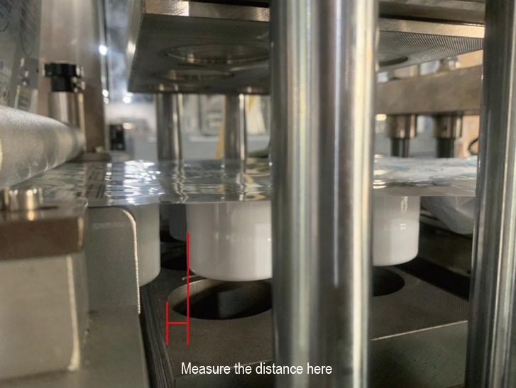
We can also measure the offset between the blister and the mold in advance, and turn the knob based on this figure.
(There are many ways to measure distance, just depending on yourself.)
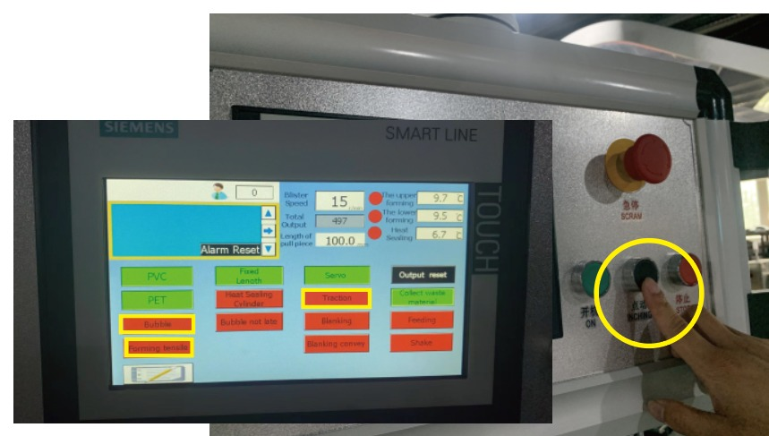
Click and turn off "bubble, traction, forming tensile" (to red color) on the touch screen, and press the jog button (beside the touch screen), to separate the upper and lower mold.
More adjustment steps will be updated soon.---->>>
This is the first part of the article,Click me to enter the second part of the article---->>>>.

 English


