Pneumatic FRL Unit Operation, Maintenance and Troubleshooting Guide (Filling & Packaging Line Exclusive)
Applicable Component: Pneumatic Air Source Two-Piece Unit (Air Source Processor, Standard Model: SMC-AC20D)
Applicable Equipment: Filling machines, packaging machines, full/semi-automatic packaging production lines, sorting and conveying lines and other pneumatic workstation equipment
Document Purpose: This guide standardizes start-up operation, daily inspection and periodic maintenance procedures. It helps operators quickly identify root causes of pneumatic faults, perform on-site troubleshooting, and ensure stable machine operation, consistent processing accuracy and high product yield for filling and packaging production lines.
1. Component Structure & Functional Description
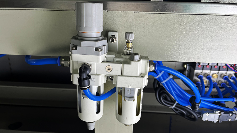
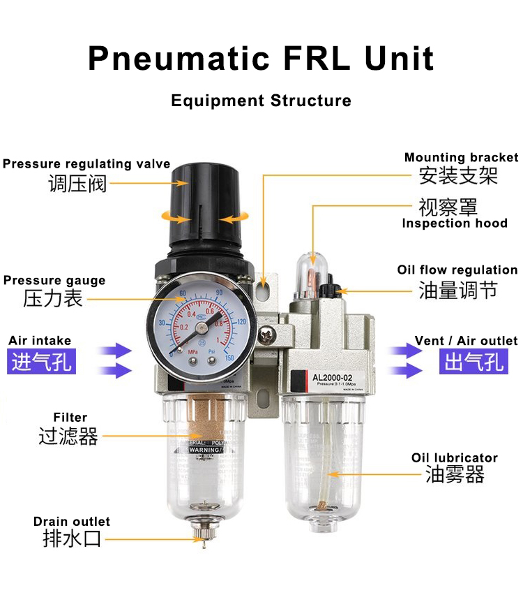
The pneumatic two-piece unit is the front-end core air processing unit of filling and packaging pneumatic systems. It consists of two modular components: an air filter regulator and an air lubricator. The air flow follows a strict LEFT IN – RIGHT OUT direction. Each structure and practical function is explained below:
1.1 Left Module: Filter Regulator (Air Filtration + Pressure Stabilization)
Pressure Adjustment Knob (Top): Unlock by pulling up to adjust output air pressure; push down to lock the set pressure. Prevents pressure deviation caused by machine vibration during production.
Filter Bowl & High-Precision Filter Element (Transparent Lower Section): Traps condensed water, dust and rust particles in compressed air. It serves as the core protection barrier for clean air, preventing filling valve blockage and seal scratch damage on packaging pneumatic components.
Bottom Drain Structure: Standard manual drain valve for discharging accumulated water in the filter bowl. High-end versions feature automatic draining, suitable for 24/7 continuous production lines.
Quick-Connect Air Fittings: Standard interface for fast connection between pipeline air sources and equipment pneumatic actuators.
1.2 Right Module: Air Lubricator (Pneumatic Component Lubrication)
Oil Flow Adjustment Screw (Top): Precisely controls lubricant dripping and atomization rate to match high-frequency reciprocating pneumatic movements on packaging and filling stations.
Transparent Oil Reservoir Bowl: Stores dedicated pneumatic turbine oil. Visual oil level observation enables convenient daily refilling.
Oil Drop Observation Window: Allows real-time visual inspection of oil supply status during machine operation to confirm normal lubrication performance.
Series Pipeline Connector: Receives filtered and stabilized clean air to complete integrated air purification, pressure regulation and lubrication processing.
1.3 Auxiliary Mounting Accessories
Includes metal mounting bracket and module locking clips. These fix the two-piece unit firmly on the machine frame to prevent component loosening, air leakage and position offset caused by production vibration.
2. Working Principle & Line-Specific Functions
2.1 Air Filtration Function (Guarantees Production Yield)
Compressed air from air compressors contains moisture, dust and rust contaminants. Unfiltered air will cause filling valve jamming and leakage, sealing cylinder wear, labeling offset and loose packaging sealing. The built-in filter thoroughly cleans the air source, eliminating packaging defects, material waste and unexpected machine stops caused by contaminated air.
2.2 Pressure Stabilization Function (Ensures Consistent Processing Accuracy)
Air compressor output pressure fluctuates during operation. This regulator balances pressure through internal valve, spring and diaphragm force equilibrium, stabilizing working pressure at the standard range of 0.4~0.6MPa for packaging and filling equipment. It prevents over-pressure damage such as crushed packages, over-filling and seal failure, as well as under-pressure issues including weak sealing, insufficient filling volume, label skew and slow cylinder movement, ensuring uniform product specifications.
2.3 Oil Atomization Lubrication Function (Extends Equipment Service Life)
Clean and stabilized air flows through the lubricator and generates negative pressure to convert dedicated lubricant into micron-level oil mist. The oil mist is delivered to high-frequency moving parts including filling cylinders, sealing actuators, labeling mechanisms and line stoppers. It continuously lubricates pistons, seals and valve cores, reducing dry friction, delaying seal aging and cracking, and lowering replacement frequency and maintenance costs of pneumatic parts.
3. Standard Operating Procedures (Start-up / Pressure Adjustment / Shutdown)
This chapter defines mandatory operational standards for on-site operators. Standard operation avoids over 80% of common pneumatic process faults and equipment wear.
3.1 Pre-Start Inspection (Daily Before Production)
Confirm air flow direction: strictly follow LEFT IN – RIGHT OUT. Reverse installation causes lubrication failure and invalid pressure regulation.
Check water level in the filter bowl. Drain water immediately if the volume exceeds 1/2 of the bowl; never start production with accumulated water.
Check oil level in the lubricator bowl. Refill dedicated pneumatic turbine oil if below the minimum scale. Do NOT use engine oil or gear oil.
Check all fittings and bowls for looseness and air leakage; ensure the entire unit is firmly mounted without shaking.
3.2 Standard Pressure Setting (Core Process Step)
Slowly open the main air valve to supply compressed air to the unit.
Pull up the pressure knob to unlock, rotate slowly and adjust the gauge pressure steadily to 0.4~0.6MPa (follow specific process requirements).
Push the knob down to lock the pressure and prevent offset from machine vibration.
Fine-tune the lubricator adjustment screw to achieve uniform oil dripping. No oil drop or excessive dripping during operation is abnormal.
3.3 In-Production Patrol Inspection (Continuous Monitoring)
Monitor the pressure gauge constantly to ensure stable pressure without fluctuation or pressure drop.
Confirm continuous and uniform oil mist supply, no interruption or over-lubrication.
Check for bowl water overflow and abnormal air leakage noise.
3.4 Standard Shutdown Procedure
After line stop, close the main air valve first and release residual pipeline pressure.
Completely drain water from the filter bowl to avoid impurity accumulation and pipeline corrosion during standby.
Check and replenish lubricant if low, preparing for the next start-up.
4. Hierarchical Maintenance Standards (Practical & Executable)
Classified daily, weekly and monthly maintenance effectively prevents air source failures, process instability and excessive equipment wear.
4.1 Daily Maintenance (Before & After Shift)
Manually drain condensed water from the filter bowl to prevent water entering downstream pneumatic circuits.
Check lubricant level and refill in time to maintain normal lubrication performance.
Visual inspection for air leakage, stable pressure and normal oil atomization status.
4.2 Weekly Maintenance (Weekly Stop for Servicing)
Clean dust and oil contamination on filter elements and bowls; inspect for clogging, darkening or damage.
Clean drain valve impurities to ensure smooth draining without jamming.
Calibrate working pressure and verify locking function to prevent automatic pressure drop.
4.3 Monthly Maintenance (Regular Equipment Servicing)
Disassemble and clean filter elements and internal valve passages to remove accumulated dirt and impurities.
Inspect sealing rubber rings on bowls and connectors; replace immediately if aging, hardening or loose.
Test lubricator atomization performance and clean atomization holes to avoid oil passage blockage.
4.4 Prohibited Operations (Critical Safety & Process Rules)
Do NOT operate equipment without lubrication. Dry running causes rapid cylinder and seal wear and permanent damage.
Do NOT clean plastic bowls with organic solvents, which will cause cracking, deformation and air leakage.
Do NOT operate under over-pressure conditions. Excessive pressure damages pneumatic seals and causes process defects.
Do NOT delay filter replacement or water draining. Contaminated air sources lead to mass defective products.
5. Fault Root Cause, Phenomenon & Targeted Solutions
Each fault item below includes root cause + equipment symptom + step-by-step troubleshooting + final solution to support fast on-site recovery for filling and packaging lines without repeated trial and error.
5.1 Fault 1: Weak Movement, Loose Clamping, Incomplete Filling/Sealing
Root Cause: Insufficient supply pressure, partial air passage blockage, pipeline air leakage
Equipment Symptom: Loose product clamping, insufficient filling volume, weak sealing force, slow labeling movement and reduced line operating speed
Troubleshooting & Solution:
Check pressure gauge; readjust and lock pressure if lower than 0.4MPa.
Inspect connectors, tubing and bowl interfaces for air leakage; fasten loose parts and replace aging seals.
Check filter element clogging; clean or replace the filter to restore smooth air flow.
5.2 Fault 2: Jittery Movement, Position Offset, Mass Defective Products
Root Cause: Failed pressure stabilization, jammed valve core, aging diaphragm, unstable air pressure fluctuation
Equipment Symptom: Jittery cylinder movement, skewed labels, wrinkled seals and inconsistent filling accuracy leading to batch defects
Troubleshooting & Solution:
Continuous gauge pressure fluctuation confirms regulator module failure.
Disassemble the regulator valve body, clean internal dirt and repair jammed valve cores.
Replace the regulator module if the diaphragm is aging or damaged, then recalibrate working pressure.
5.3 Fault 3: Frequent Cylinder/Solenoid Valve Leakage & Jamming
Root Cause: Failed filtration, water and impurities in air source causing seal abrasion and component jamming
Equipment Symptom: Frequent workstation jamming, air leakage noise, intermittent machine alarms and rising component failure rate
Troubleshooting & Solution:
Check for overflowing bowl water and damaged/invalid filter elements.
Replace with a new filter element and completely remove water and impurities from the air circuit.
Clean rust and contaminants in downstream pneumatic components to prevent secondary jamming.
5.4 Fault 4: Noisy & Dry Pneumatic Movement, Rapid Component Aging
Root Cause: Lubricator failure, no oil supply or abnormal oil delivery leading to dry friction operation
Equipment Symptom: Abnormal cylinder operation noise, dry and sluggish movement, cracked seal leakage and shortened component service life
Troubleshooting & Solution:
No oil drop observed through the window confirms lubrication failure.
Check oil level and refill dedicated pneumatic turbine oil if empty.
Fine-tune the oil adjustment screw and clean blocked atomization holes and oil passages.
Verify correct air flow direction and correct reverse installation to restore normal oil mist delivery.
5.5 Fault 5: No Pneumatic Movement, Station Shutdown
Root Cause: Fully clogged filter element, blocked air passage and zero air output
Equipment Symptom: All pneumatic stations stop working; machine fails to start and production line shuts down
Troubleshooting & Solution:
Turn off main air supply, remove and replace fully clogged filter element.
Clean internal valve body blockage and check tubing for bending or squeezing.
Test air circuit patency, calibrate pressure and resume production.
5.6 Fault 6: Continuous Air Leakage from Two-Piece Unit
Root Cause: Loose bowl installation, aging/damaged seals and loose valve connectors
Equipment Symptom: Continuous air leakage noise, slow pressure drop and insufficient machine power
Troubleshooting & Solution:
Retighten filter and oil bowls to ensure full thread and clip locking.
Inspect all sealing gaskets and replace aging, missing or damaged parts.
Fasten valve body connector screws to eliminate interface gaps and air leakage.
6. Fault Summary & Prevention Guidelines
Over 90% of pneumatic process defects, machine jamming, component damage and line downtime on filling and packaging lines are caused by abnormal pressure, humid air source, insufficient lubrication, filter clogging and seal leakage. Strictly implement the daily inspection and maintenance standards in this manual to eliminate most pneumatic faults fundamentally, stabilize product yield and reduce maintenance costs and production loss.

 English