Systematic Troubleshooting & Solution Guide for Poor Induction Sealing of Aluminum Foil Gaskets
Abstract: Wrinkled aluminum foil gaskets and sealing leakage during induction sealing are rarely caused by a single equipment fault. They result from combined abnormalities in gaskets, bottle-neck quality, gasket insertion, capping torque and induction sealing parameters. This guide provides complete, practical troubleshooting and optimization solutions covering theoretical principles and real-world production cases. |
Poor sealing caused by wrinkled aluminum foil gaskets under induction sealing is seldom triggered by one single factor. Five key areas shall be inspected systematically: gasket selection, bottle-neck quality, gasket insertion method, capping control, and induction sealing parameters.
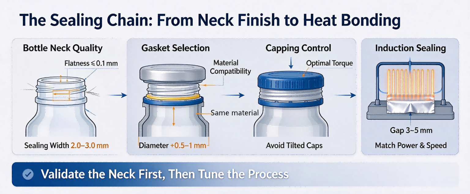
Core Principles: The bottle neck must be flat; the gasket shall lie flat inside the cap; uniform compression shall be applied to the gasket against the bottle neck after capping; and precise thermal bonding shall be achieved during induction heating. |
1. Gasket Selection: Material, Dimension and Thickness
Improper incoming-material matching is frequently the root cause of gasket wrinkling and sealing failure.
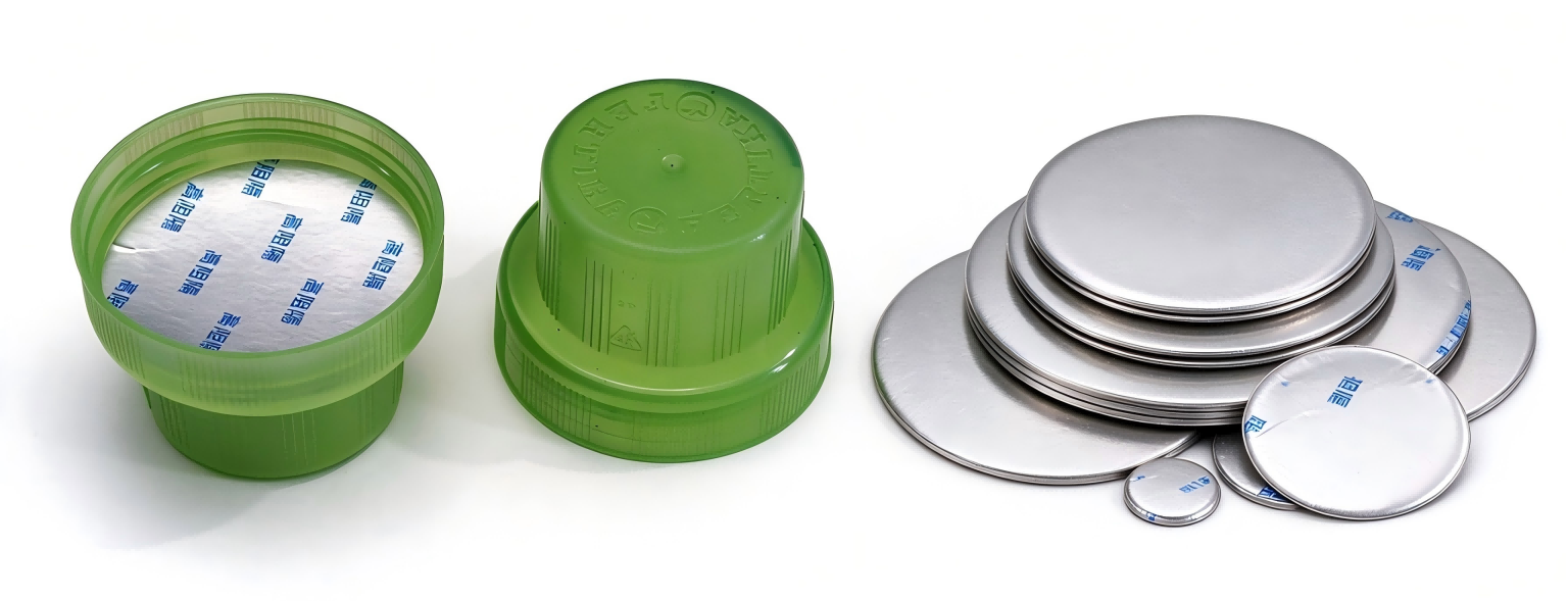
1.1 Material and Composite Structure
An aluminum foil gasket is a multi-layer composite structure: backing board + aluminum foil + heat-seal layer. The heat-seal layer must be compatible with the bottle material, which forms the foundation of reliable sealing.
• PE / HDPE bottles: Use gaskets with PE heat-seal layer
• PP bottles: Use gaskets with PP heat-seal layer
• PET bottles: Use dedicated PET-compatible gaskets. Even if aluminum foil heats up, mismatched heat-seal layers cannot fuse with the bottle neck.
• Glass bottles: Use glass-bottle-specific gaskets with matched temperature resistance.
Note: The peel strength between composite layers shall not be lower than 2 N/10 mm. Insufficient peel strength leads to edge delamination during die-cutting or insertion, and blistering under heat in finished products. |
1.2 Dimension: Slightly Larger than Bottle Neck, but Not Excessively Large
The gasket diameter shall be 0.5–1 mm larger than the bottle-neck diameter. This margin ensures full coverage of the sealing surface and slight edge compression after capping.
• Too small: The gasket fails to fully cover the bottle neck, directly causing liquid leakage.
• Too large: Gasket edges curl or get caught under cap barbs during insertion. Forced capping creates wrinkles; thermal contraction during sealing further deforms the foil.
1.3 Thickness: Precise Matching with Inner-cap Cavity
Gasket thickness must match the gap between cap inner base and bottle-neck end face.
• Over-thick gasket: Excessive compression during capping generates wavy wrinkles.
• Over-thin gasket: Clearance exists between gasket and bottle neck; effective compression cannot be built after capping.
Common available thickness: 0.6 mm, 0.95 mm, 1.05 mm.
On-site verification: After capping, no visible gap shall exist between cap and bottle neck, and the gasket shall be compressed evenly. |
2. Bottle-neck Quality: The Foundation of Sealing
The bottle-neck end face is the direct contact surface for foil thermal bonding. Defects on the bottle neck create a vicious cycle with gasket wrinkling:
Uneven end face → Partial gasket floating / uneven stress → Partial weak seal after induction → Leakage upon cooling |
2.1 Sealing-face Width
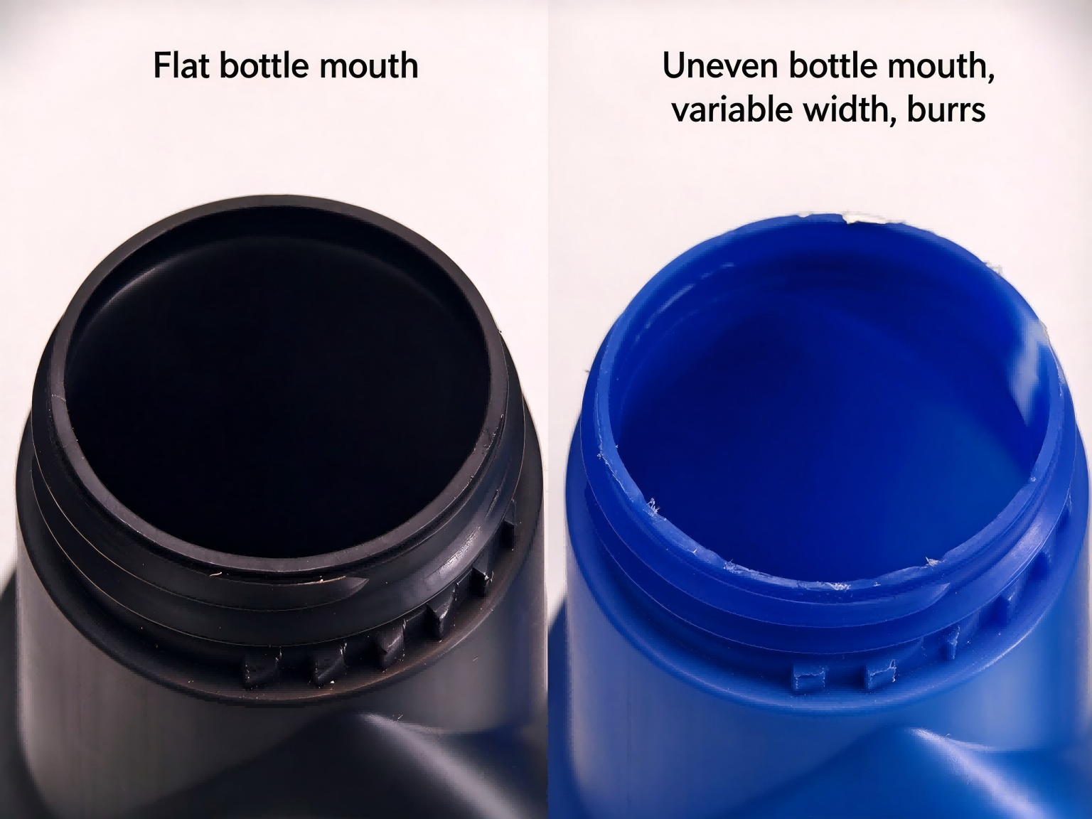 Sealing-face width refers to the radial width of the annular flat surface where the bottle-neck end face bonds to the gasket heat-seal layer.
• Minimum requirement: Effective sealing width ≥ 1.5 mm. Insufficient bonding area causes edge lifting and leakage under transportation vibration or internal pressure fluctuation.
• Recommended range:2.0–3.0 mm. This ensures at least 0.5 mm overhang margin for the gasket and prevents edge folding and wrinkling.
• Inspection method: Measure outer and inner diameters of bottle-neck end face with a projector or calibrated magnifier. Divide the diameter difference by two to obtain single-side sealing width. Record maximum and minimum values during sampling inspection.
2.2 Flatness of Bottle-neck End Face
Uneven bottle-neck end face is the top cause of gasket wrinkling and crescent-shaped partial non-sealing.
• Requirement: Continuous, complete flat end face without visible warping, dents or saddle-shaped undulation.
• Tolerance: Flatness ≤ 0.1 mm. Excessive flatness error causes over-compression (even foil piercing) at high spots and gaps / weak sealing at low spots.
• Saddle-shape risk: High points at 12-o'clock & 6-o'clock and low points at 3-o'clock & 9-o'clock (or reversed). High-position areas produce wrinkles under capping torque while low-position areas lose contact, resulting in leakage originating from low spots.
• Inspection method: Place bottle neck upside-down on glass or marble plate, check for light leakage or wobbling. A 0.1 mm feeler gauge insertible at multiple positions indicates non-conformance.
2.3 Burrs and Protruding Spots
Burrs and protruding spots act as local high points that pierce aluminum foil or lift gaskets to form leakage channels.
• Burrs: Originating from mold parting lines or worn trimming blades. No burrs shall exist on inner / outer edges of bottle-neck end face. Burrs puncture foil and create pinhole leakage. Inspection: Run fingertips gently over end face or wipe with absorbent cotton; cotton snagging indicates burrs.
• Protruding spots: Plastic particles or unmelted resin on sealing surface. They lift local gasket areas and create annular gap leakage. Inspection same as burr check; catch when scratching with fingernail.
2.4 Cracks and Defects
• Notches / chips: Radial notches on end face are unacceptable. Sealing surface discontinuity leads to direct product leakage.
• Cracks vs stress whitening: Actual cracks must be rejected. Stress whitening from injection / blow-molding stress may develop into cracks under capping force or temperature variation; it is a high-risk defect requiring control and sorting.
• Sink marks / dents: Local depressions create low-pressure zones, leaving gaps between gasket and neck and causing spot leakage.
• Inspection: Visual check under sufficient light with magnifier. For critical applications such as pharmaceutical or oil bottles, 100% automatic optical inspection (AOI) is recommended.
2.5 Bottle-neck Quality Control Recommendations
1. Establish incoming inspection standards: Include sealing-face width, flatness, burrs, protrusions and visual defects for pre-forms and finished bottles.
2. Collaborate with bottle suppliers: Burrs are mostly related to trimming processes; saddle-shaped deformation comes from uneven mold cooling or mold wear. Submit leak-failure samples (especially parts with crescent non-bonded areas after peeling foil) to suppliers for mold root-cause analysis.
3. Validate bottle-neck quality before machine tuning: Run sealing tests using qualified bottles. Even well-optimized sealing parameters cannot compensate for inherent bottle-neck defects.
3. Gasket Insertion: Avoid Pre-formed Wrinkles
The insertion station is a primary source of gasket wrinkles. Traditional mechanical push-plate feeding creates micro-wrinkles via lateral shear force on gaskets.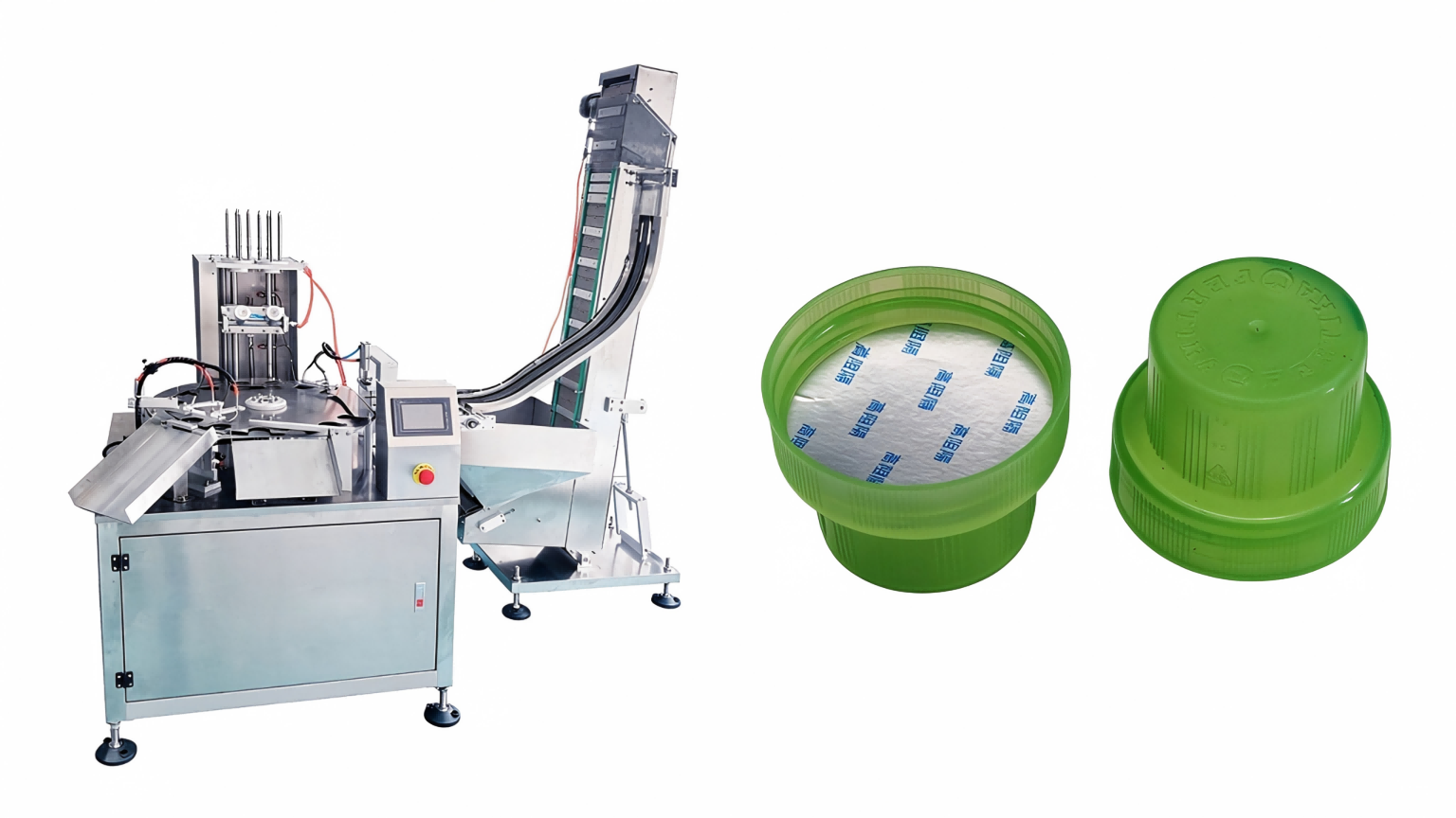
1. Vacuum suction + vertical insertion: Replace push plates with suction heads. The suction head picks gaskets vertically from the bottom of the magazine and presses straight down into cap inner base. No lateral shear force, maintaining maximum flatness.
2. Tapered suction-head sidewall: For caps with internal barbs, tapered geometry allows gaskets to deform conically during insertion and smoothly pass over barbs without jamming or wrinkling.
3. Air-evacuation to prevent air bulges: Extract trapped air inside caps during pressing-in. Air bulges under gaskets cause uneven compression during sealing.
4. Capping Machine Control: Uniform Compression is Essential
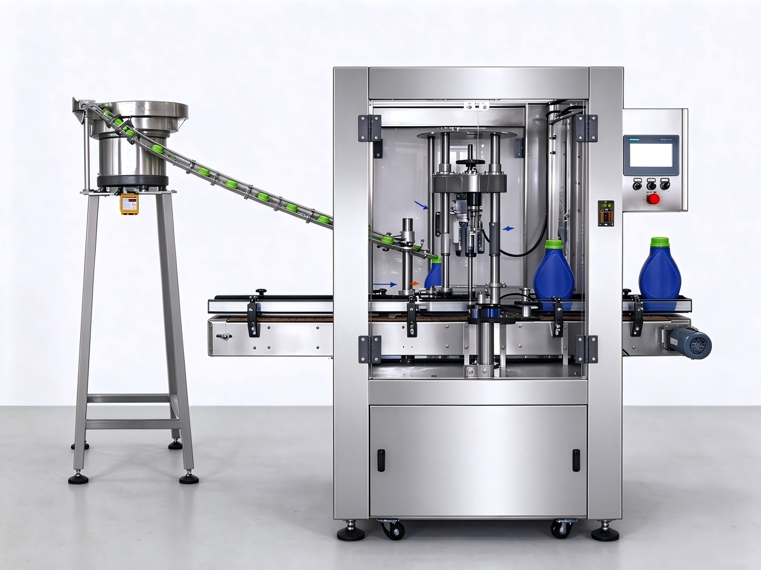
Capping aims to press gaskets evenly against bottle necks — tighter torque does not equal better sealing.
4.1 Torque Setting
Excessive capping torque is a common cause of radial gasket wrinkles, generated by squeezing gasket edges between bottle neck and cap barbs.
• Acceptance criteria: After capping, no perceptible rotation when manually re-tightening, while cap deformation and gasket wrinkling shall not occur.
• Tuning: Gradually reduce clamping / capping torque and observe wrinkle improvement. Too low torque causes gasket shifting during sealing; too high torque worsens wrinkling. Find the optimal middle range.
4.2 Capping Wheel and Conveyor Stability
• Ensure uniform contact pressure of capping wheels against caps. Tilted caps result in over-pressure on one gasket side and floating on the opposite side, leading to partial leakage.
• Keep conveyor horizontal and stable. Bottles shall not wobble or tilt between capping and induction sealing station.
5. Induction Sealer: Parameter Optimization for Convex-top Caps
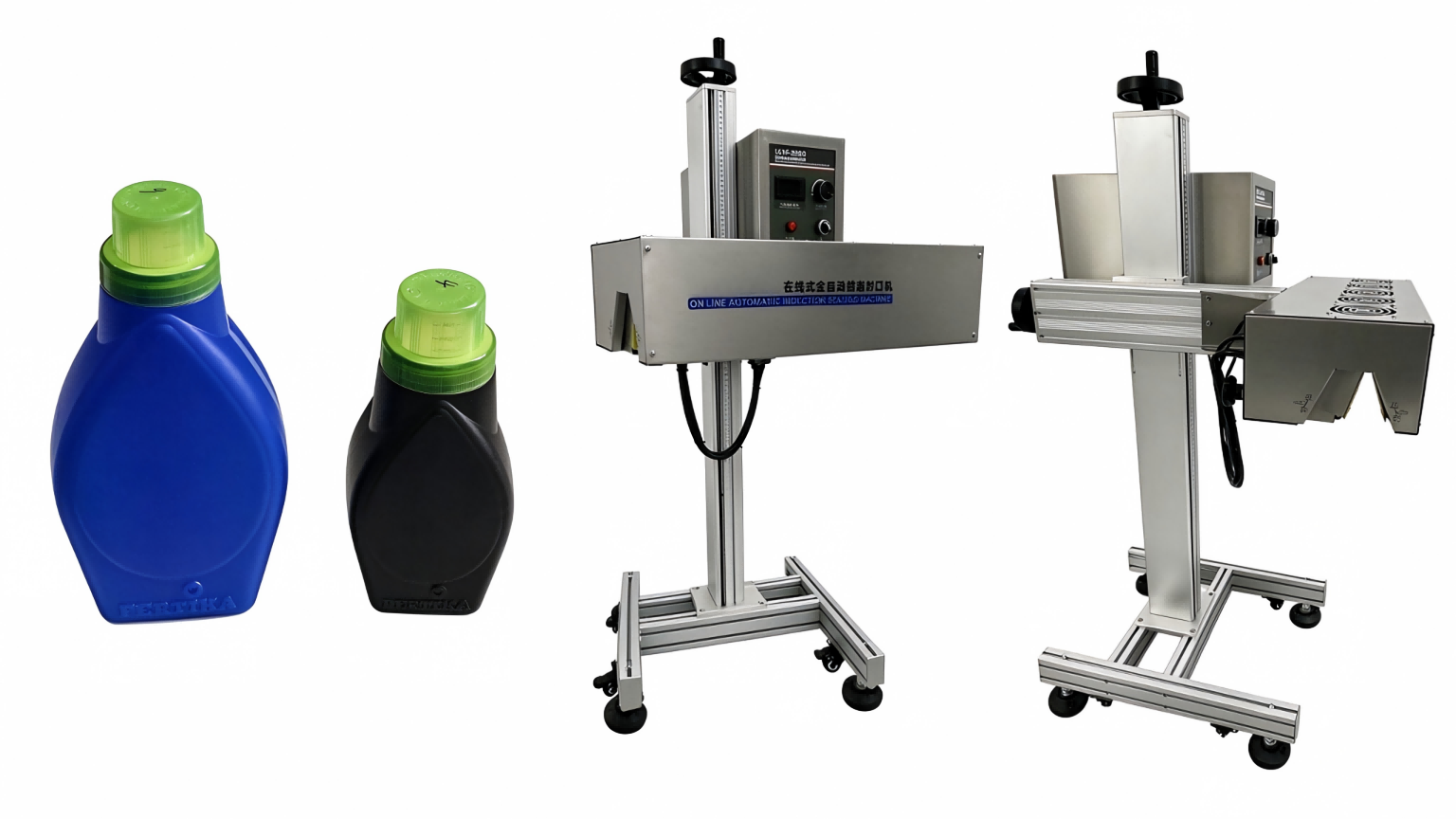
Convex-top caps change the vertical position of aluminum foil relative to induction coils. Coil configuration and process parameters need targeted adjustment.
5.1 Coil Shape and Working Distance
• Coil profile adaptation: Standard flat coils produce uneven magnetic-field distribution for convex-top caps. Custom or reshaped coils matching cap top contour help magnetic field penetrate through cap material to reach aluminum foil.
• Critical gap: Maintain vertical distance between coil and aluminum foil at 3–5 mm. Measure physically for convex-top caps. Distance > 5 mm leads to insufficient heating; distance < 3 mm risks cap burning.
5.2 Power and Conveyor-speed Matching
Over-power causes premature thermal shrinkage of aluminum foil before heat-seal layer fully melts and bonds, creating sealing wrinkles.
• Tuning procedure: Start with appropriate power level according to machine rating and test with relatively low conveyor speed.
• Post-sealing evaluation after cooling: Peel off foil. Qualified result: flat wrinkle-free foil, heat-seal layer uniformly transferred and bonded to bottle-neck end face.
• Wrinkled / burnt foil: Decrease power or increase conveyor speed.
• Poor bonding: Increase power or decrease conveyor speed.
5.3 Cooling & Equipment Maintenance
1. Allow at least 1-minute cooling time post-sealing for hot-melt solidification. Avoid impact or cap opening during cooling.
2. Keep induction head surface clean. Dust and oil contamination distort magnetic-field distribution and cause uneven sealing performance.
6. Practical Production Case: 39 mm HDPE Liquid-fertilizer Bottle with Convex-top Cap
Working condition: 39 mm neck HDPE bottle, convex measuring-cup cap, liquid fertilizer filling. Common failures: sealing wrinkles and leakage. |
6.1 Gasket Selection
1. Material compatibility: HDPE bottles require PE heat-seal gaskets. Liquid fertilizer is often weakly acidic and salt-containing. Select corrosion-resistant multi-layer gaskets (PE heat-seal layer + barrier layers + aluminum foil + backing board) to prevent inter-layer delamination under chemical exposure.
2. Dimension: For 39 mm bottle neck, gasket diameter: 41–42.5 mm, providing 0.5–1.5 mm overhang,Depends on the diameter of the lid's inner edge.
3. Thickness: Measure actual gap between cap inner base and bottle-neck end face. Choose matching thickness among 0.4 / 0.6 mm / 0.8 mm to avoid compression wrinkles or insufficient pressing force.
6.2 Bottle-neck Quality Control (Critical for Blow-molded HDPE Bottles)
• Sealing-face width ≥ 1.5 mm; preferred 2.0–3.0 mm.
• Flatness ≤ 0.1 mm. Pay special attention to blow-molding-induced saddle-shape undulation which creates crescent-shaped weak seals.
• Remove all flash and trimming burrs on blow-molded necks to prevent foil piercing and leakage.
• On-site test: Upside-down neck on glass plate for light-leakage check; 0.1 mm feeler-gauge test; cotton-wiping for burr detection.
6.3 Gasket Insertion
Convex measuring-cup caps feature deep inner cavities and anti-release barbs. Mechanical push-plate insertion is not recommended.
Solution: Vacuum-suction vertical-press gasket inserter with tapered suction head to cross internal barbs. Add post-insert pressing mechanism to ensure gaskets lie flat without edge curling. |
6.4 Capping-machine Tuning
For convex measuring-cup caps, the capping system must realize firm gripping without damaging the measuring-cup structure.
1. Torque range: Lower limit — no manual re-twist rotation after capping; Upper limit — no cap deformation or radial gasket wrinkles.
2. Servo-capping recommendation: Two-stage control: low-speed screwing-in, decelerate and ramp-up torque upon threshold to avoid over-torque from inertial impact.
3. Profile-matching capping heads: Use profile-matching capping heads for convex caps to prevent concentrated pressure and cap tilting. Sample-check finished caps to exclude tilted-cap flow to sealing station.
6.5 Induction-sealer Adjustment
1. Physically measure coil-to-foil gap and keep it within 3–5 mm. Convex-top caps frequently suffer from excessive gap leading to insufficient heating.
2. Parameter tuning: Low-power machines start at higher power setting; high-power machines start at medium-low power, combined with slow conveyor speed.
○ Wrinkled foil / melted neck surface: Reduce power or raise conveyor speed.
○ Easy-to-peel seal / no separation between foil and backing board: Increase power or reduce conveyor speed.
3. Pre-production requirement: Threads and sealing end face must be dry and clean after filling. Residual fertilizer droplets cause uneven heating and spot leakage.
7. Summary
Reliable induction-sealing performance depends on coordinated performance across five modules.
Module | Core Requirement | Key Control Points |
Gasket | Material compatibility, slight over-dimension, 0.4mm thickness matching | Heat-seal layer matches bottle material; gasket diameter +1–1.5 mm vs neck; thickness verified by actual measurement |
Bottle Neck | Flat, burr-free, defect-free | Flatness ≤ 0.1 mm; sealing-face width 2.0–3.0 mm |
Insertion | Vertical feeding, no lateral shear force | Vacuum suction instead of mechanical push-plate feeding |
Capping | Uniform compression, avoid over-torque | Proper torque setting; prevent tilted caps |
Induction Sealing | Precise gap, matched power & speed | Coil-to-foil gap 3–5 mm; tune parameters based on machine specification |
The bottle neck forms the foundation of sealing. Even with optimized gaskets, insertion and capping, leaks will still occur if the neck surface is uneven or burr-contaminated. When troubleshooting sealing-leakage issues, prioritize bottle-neck flatness and burr inspection. Optimize gasket specification, insertion mechanism, capping torque and induction-sealing parameters systematically to resolve sealing-failure problems. |
---------------------------------------------------------------------------------------------------------------------
Please contact me for guidance on selecting the right equipment for your bottling line.
Ava Duan
whatsapp/wechat:86-13706885851
Email:sales@grand-packing.com

 English
 Sealing-face width refers to the radial width of the annular flat surface where the bottle-neck end face bonds to the gasket heat-seal layer.