1. Printing station & earbelt welding station
These two stations associate to each other, so they are analyzed here together.
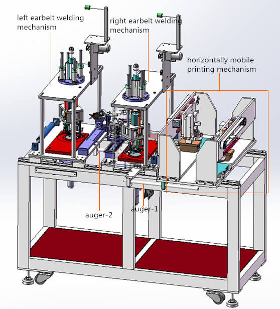
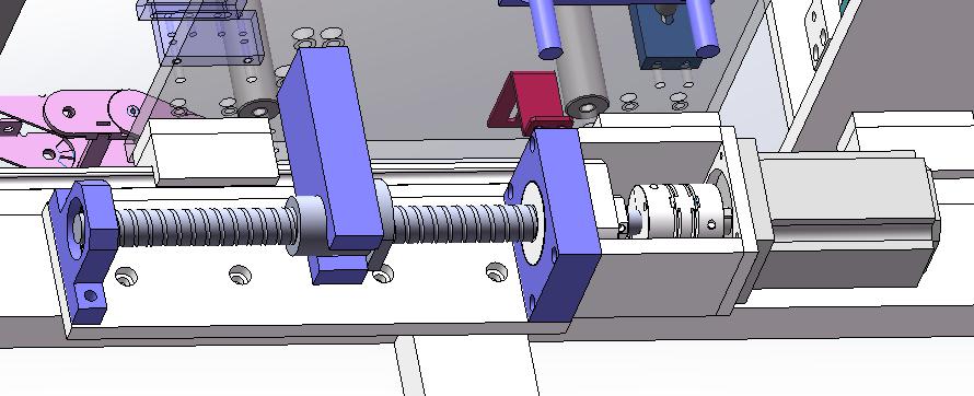
It can be seen that two augers are used to connect the left and right earbelt welding mechanism. Meanwhile, they together move along the guide on machine frame. The driver is the servo motor and screw mechanism under the machine frame.
But, why do they moves?
The reason is that: cloth material is moving forward, while the mobile printing mechanism and earbelt welding mechanism should contact material during operation. Therefore, there should be no relative movement between these mechanisms and material while contacting. For this reason, mobile printing mechanism and earbelt welding mechanism should move forward with material and return after their separation from material.
1) Mobile printing station
We can find texts on N95 like this:
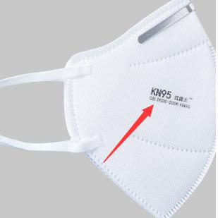
It is exactly printed by this station.
The following is its particular structure:
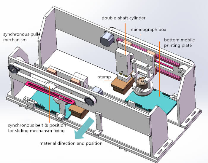
First of all, the working principle of both left and right mobile printing mechanisms is the same.
The rear stamp and mimeograph box is driven by synchronous belt and guide mechanism. Motor drives synchronous pulley to fix sliding mechanism and synchronous so that they can take a linear motion.
a. Motion order (techniques)
a) Coating colorant on bottom mobile plate with mimeograph box;
b) Stamp moves to the top of mobile plate; double-shaft cylinder lowers and presses the stamp to stick colorant;
c) At last, the stamp will move up to the material. Double-shaft cylinder lowers and colorant is stamped onto material.
2) Earbelt welding station
Left and right earbelt welding mechanisms have the same structure and working principle but opposite position.
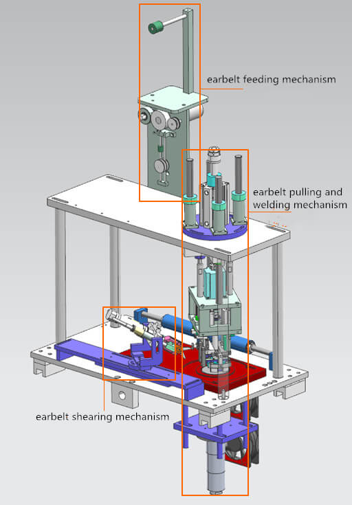
Operation flow:
a) Earbelt is fed by feeding mechanism and pulled to welding mechanism;
b) Earbelt pulling and welding mechanism pulls earbelt and then sheraing mechanism shears it;
c) At last the welding mechanism weld earbelt on mask.
a. Earbelt feeding mechanism
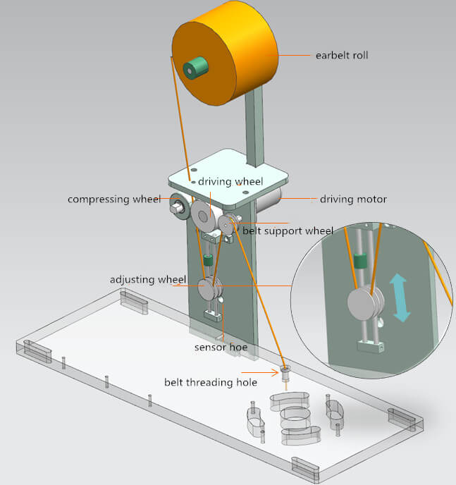
Earbelt path: earbelt roll → driving wheel&compressing wheel → adjusting wheel → belt support wheel → belt threading hole
Compressing wheel compresses earbelt onto driving wheel. As driving wheel rotates, earbelt moves downwards. At another end, earbelt connect with pulling mechanism through threading hole. However, earbelt releasing speed will not correspond to its pulling speed. In this case, adjusting wheel plays a role to adjust earbelt tension.
If it is release, earbelt will be loose and adjusting wheel falls until it is detected by sensor. Then driving motor stops. Meanwhile, pulling mechanism will continue earbelt pulling and lift the adjusting wheel. Once sensor does not detect the wheel, driving motor starts wrking again and drives earbelt to be released. This releasing motion repeats.
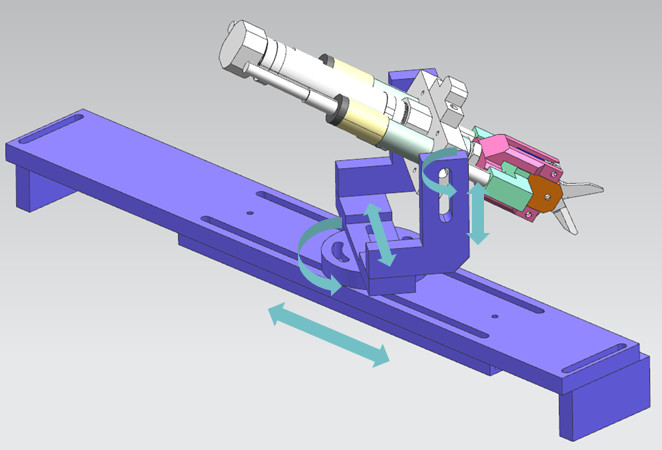
b. Earbelt pulling and welding mechanism
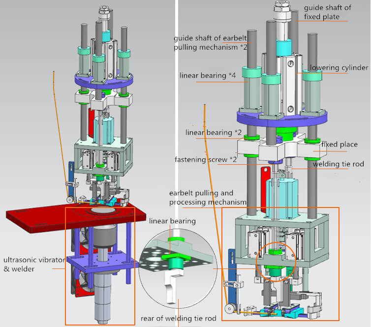
a) How are some parts connected?
The lowering cylinder drives fixing plate;
Welding tie rod is locked on the fixing plate through locking screws;
The motion between welding tie rod and earbelt pulling and processing mechanism is relative. But if the rod lifts to its bottom contacting the mechanism, the whole mechanism will then be held up.
b) Principle of vertical motion:
Lowering cylinder pushes down fixing plate;
Fixing plate pushes down welding tie rod;
Earbelt pulling mechanism held up by welding tie rod moves down due to gravity;
When pulling mechanism bottoms, the lowing cylinder will pushes down welding tie rod until it bottoms, too;
The lowering cylinder drives fixing plate to move up;
Fixing plate drives welding tie rod to move up; then the rod end touches earbelt pulling mechanism and these two parts move up together;
They moves to the limit of cylinder.
c) Earbelt pulling and welding mechanism
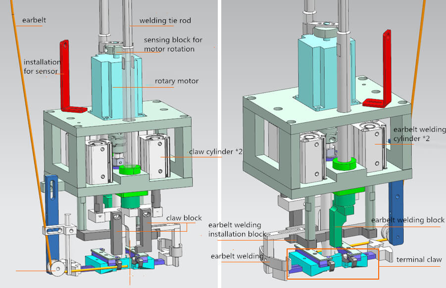
This is a picture of earbelt pulling and processing mechanism from two angles and the following one is a detail image of terminal claw:
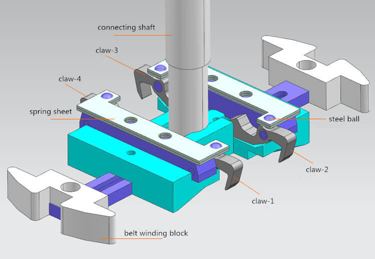
i. Functions of some parts
The sensor cooperates with motor by detecting sensing block for motor rotation to control rotation angle (180° per time)
The spring’s state can be kept by steel ball. (If it is pressed by claw block, the spring will not rebind)
Claw will be like this after it is pressed by claw block (earbelt can be pressed in case of its loosening):
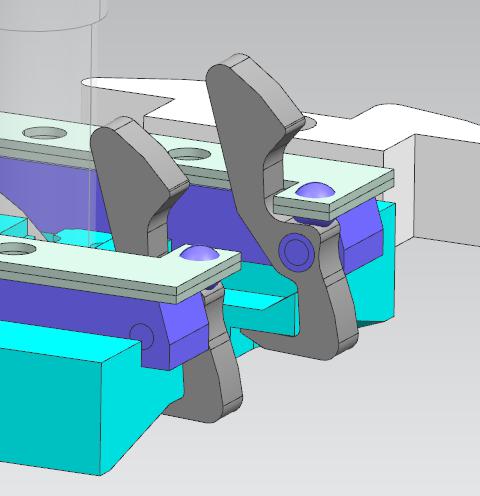
ii. Working order (the most important)
At the very beginning, earbelt is pressed by claw-1;
Rotary motor drives terminal claw to rotate for 180°. then claw-1 will automatically pull earbelt to the following state:
Claw cylinder drive claw block to lower claw and press earbelt. Then the earbelt shearing mechanism shears earbelt and return with claw block;
The whole mechanism lowers until the earbelt welding block at two sides press the two ends of earbelt;
Earbelt welding blovk weld earbelt onto mask; earbelt welding cylinder pushes welding strip down. While the strip is pushing earbelt on winding block away, the installation plate for welding strip will press the cocked end of claw-2,3 &4 to restore the three claws. At the same time, claw can release the sheared earbelt. (Note: claw 1 is not pressed);
Note: in the subsequent motions, the installation plate will press only claw2&3.
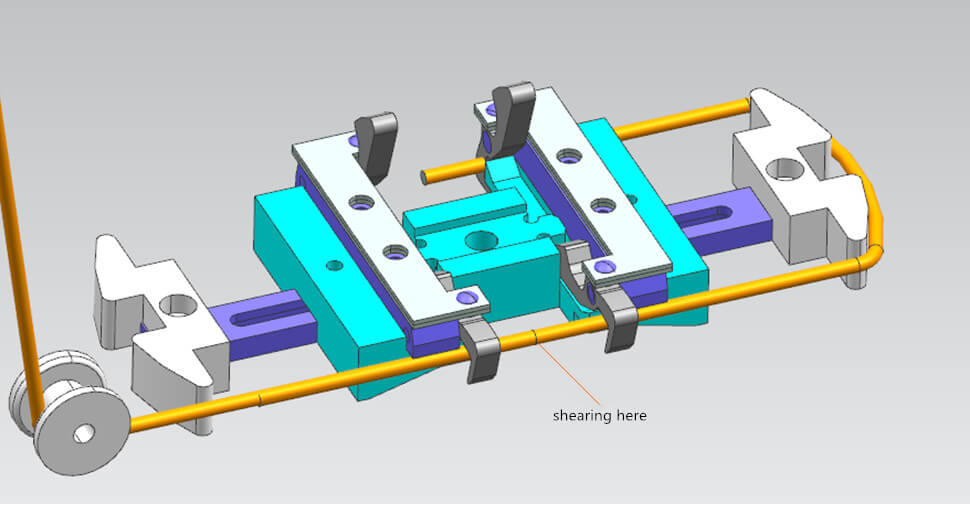
c. Earbelt shearing mechanism
The purple part is used to adjust angle and position of the mechanism.
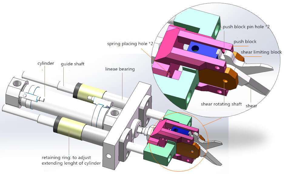
There are pins in push block pin hole and shear rotating shaft in practical production. Springs are also placed in spring placing hole. Besides, there is no connection between push block, green part and shear limiting block. They can slide.
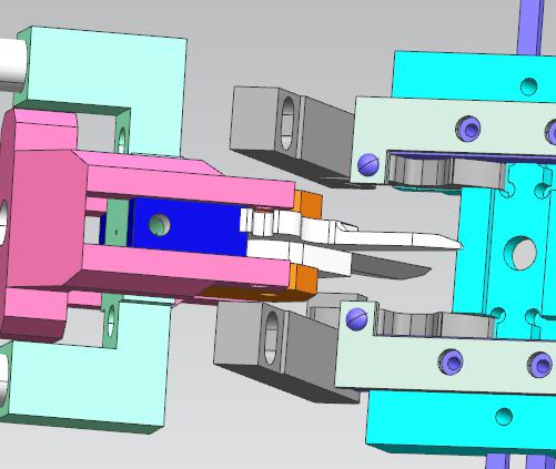
a) Working order:
Cylinder pushes front-end mechanism to earbelt;
Cylinder pushes continuously even when shear limiting block contact claw block (shown in the following image). But the shear will be pushed to be closed and so that earbelt is sheared;
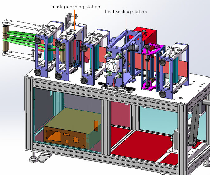
2. Mask punching and waste processing stations
1) Mask folding mechanism
As we all know, KN95 is folded. Actually, this mechanism is exactly used to fold masks.
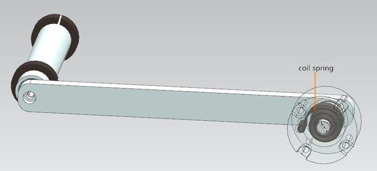
2) No-power roller station
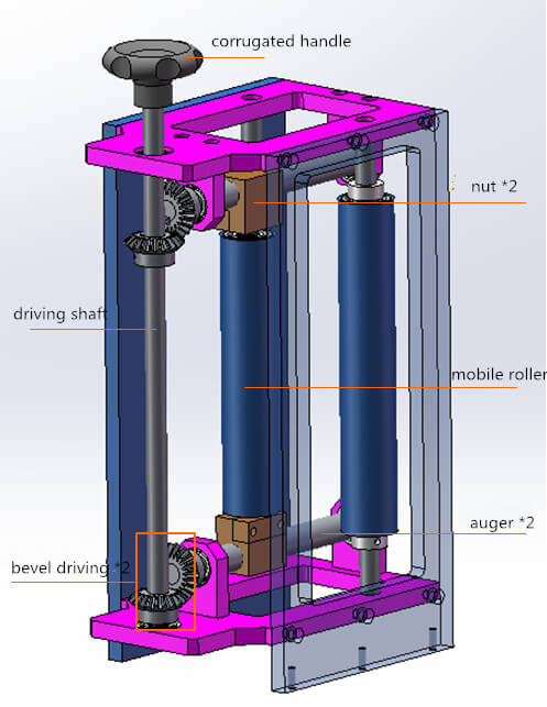
Rotating corrugated handle can drive driving shaft to rotate. Then auger is also driven to rotate by bevel driving mechanism. At last, position of mobile roller can be adjusted.
3) Mask punching station
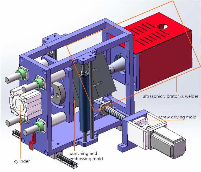
Screw driving mold drives the whole mechanism to reciprocate to make sure that there is no relative displacement of masks. The folded mask id heated by ultrasonic and punched.
4) Earbelt flip station
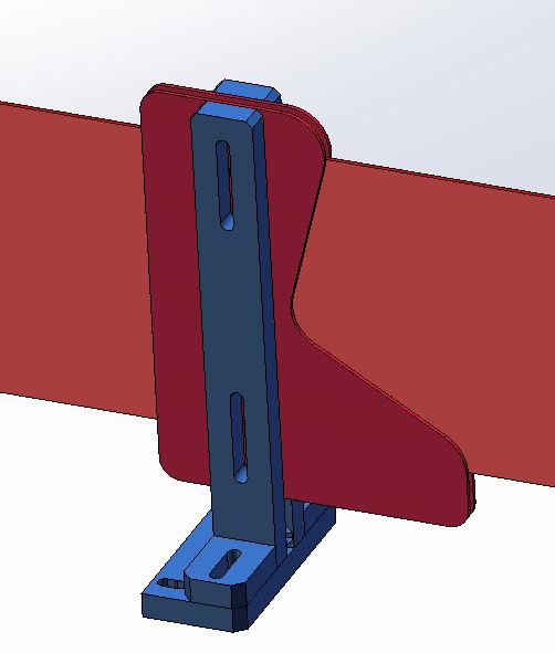
Before this station, earbelt faces down. But the earbelts of all end masks face up. Its the function of this station: to flip earbelts.
5) Mask discharging station
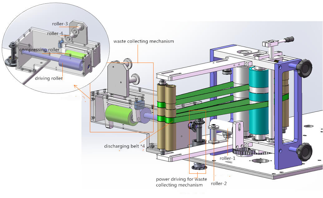
Discharging belt can discharging masks. Punched waste will be discharged in the order: roller-1 → roller-1 → roller-3 → roller-4 → driving roller&compressing roller.
The power of waste collecting mechanism also comes from the power shaft and transmitted by the bevel mechanism. But, what is the power origin of the power shaft?
It can be seen that the power origin is the servo motor and reducer. Their power can be transmitted to other stations through the power shaft.
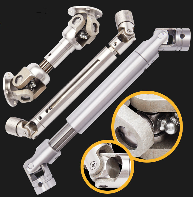
The equipment consists of multiple machine frames. To not dismantle the power shaft while separating them, flexible universal coupling is used at connecting place.

 English


