On the market, N95 are of many kinds. The N95 mask machine we introduced today, its product mask is like this:
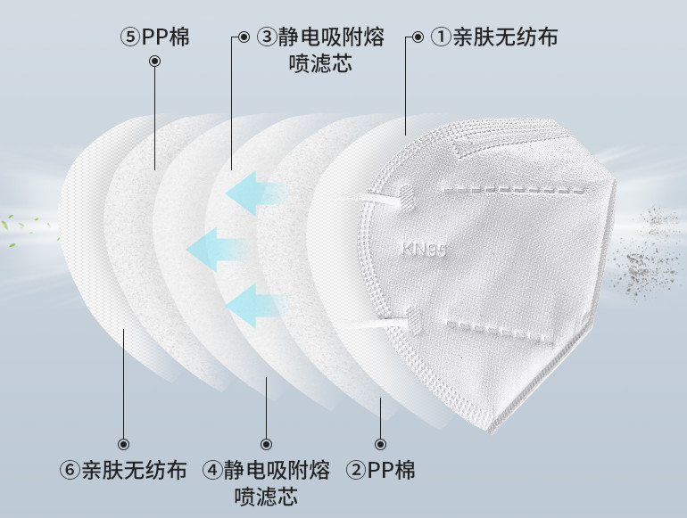
① Skin-friendly non-woven
② PP cotton
③ Electrostatic adsorption melt-blown filter
④ Electrostatic adsorption melt-blown filter
⑤ PP cotton
⑥ Skin-friendly non-woven
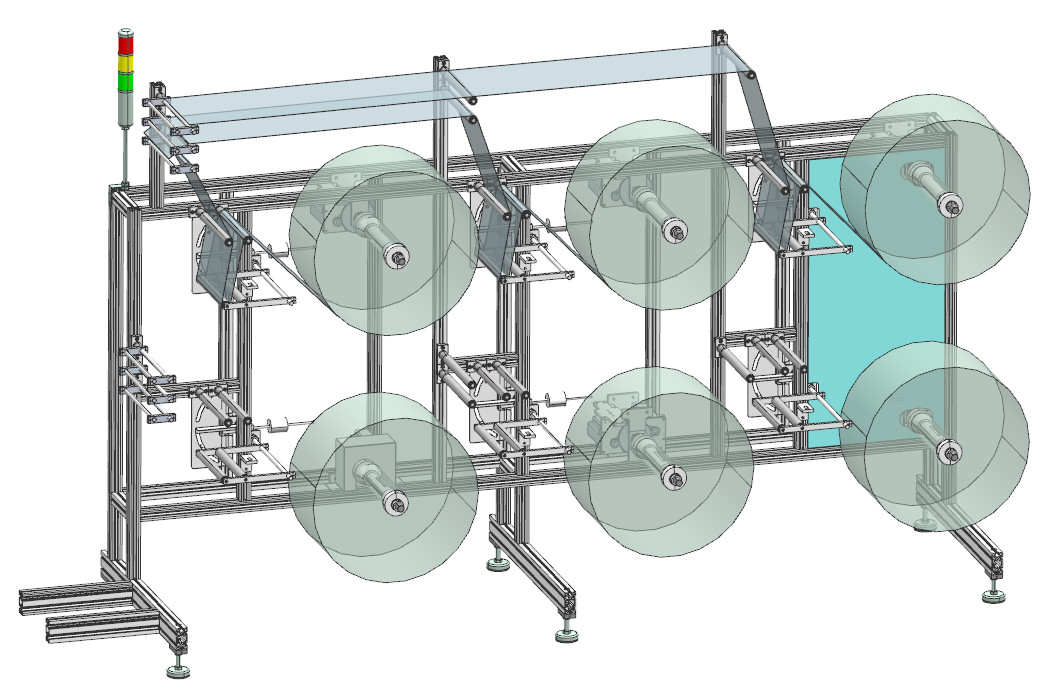
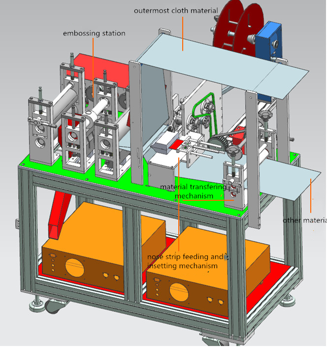
The following picture is an axonometric:
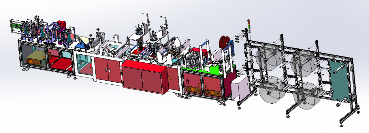
The whole process is marked as following:
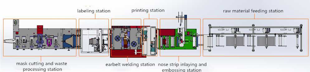
1. Raw material feeding station
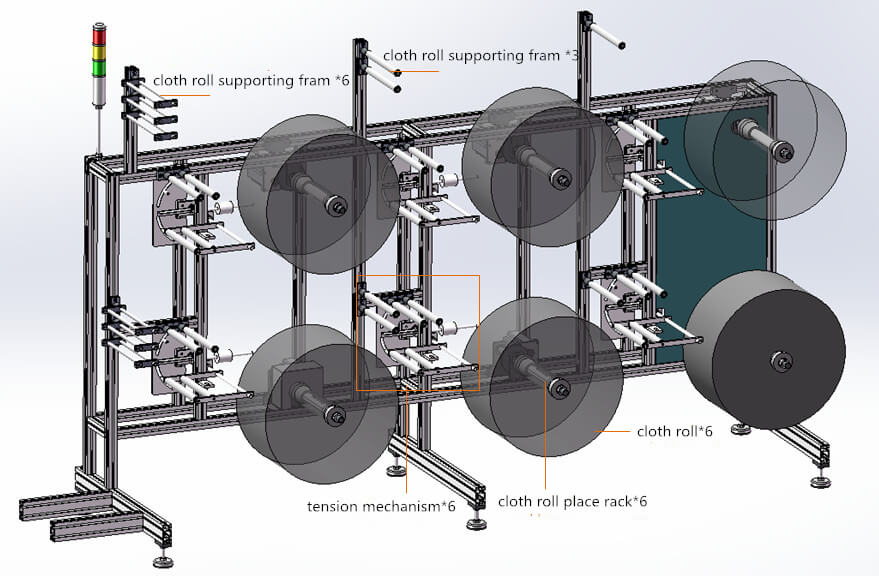
Generally N95 consists of 3-6 layer cloth and this mask machine can produce masks of 6 layers. The cloth roll quantity is determined by the end mask layer. How many mask layers, how many cloth rolls.
1) Cloth path
Every roll of cloth will first cross tension mechanism and supported by cloth roll supporting frame and connect to the next station, shown as in the following figure:
2) Station structure
a. Cloth roll place rack
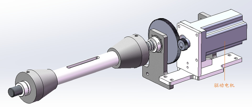
Driving motor
This device is powered by the driving motor.
b. Tension mechanism
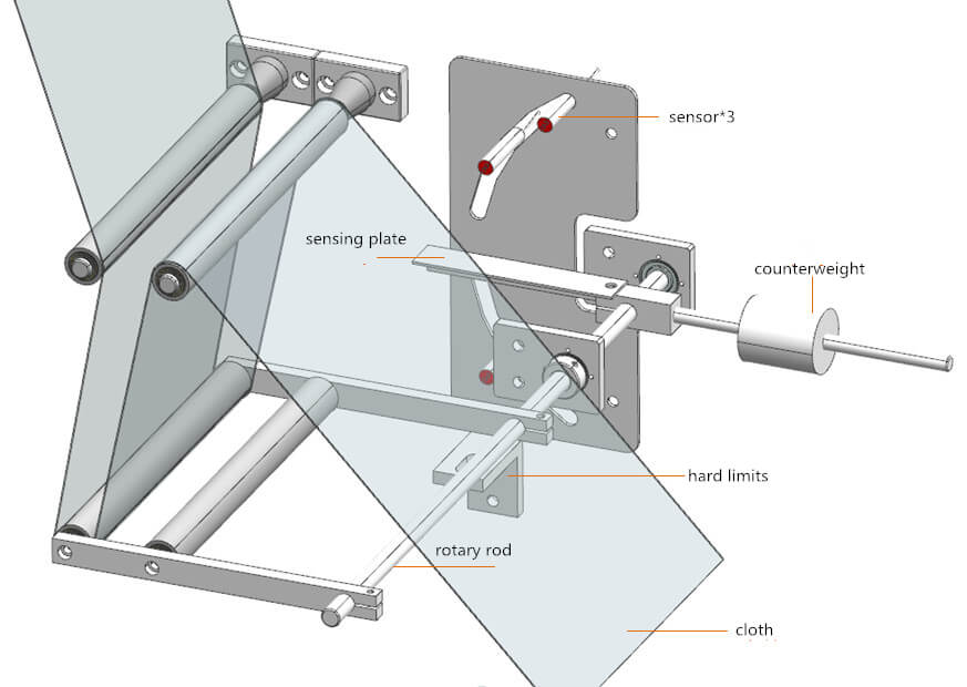
This tension mechanism can prevent cloth from being too loose or tense. Its particular principle is:
a) Cloth material is released firstly. Since material releasing speed is higher than material feeding speed during production, the material will be loose. In this case, a roller at the left of rotary rod falls due to gravity until the sensing plate is sensed by the sensor. At that time, the driving motor stop. During this process, the cloth will keep tense.
b) After driving motor stops rotation, cloth material will be tenser and tenser. Then the roller will be driven to move upwards until the sensing plate is sensed. And the material is released again.
c) The above process repeats.
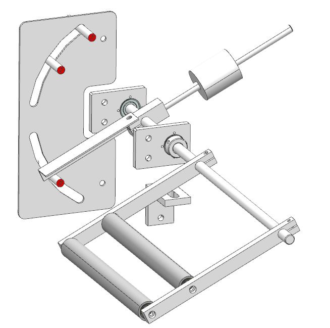
In the figure, we find a counterweight. It can reduce the downward pressure of two rollers to cloth material, but the reduced pressure is still overwhelmed by their weight. Therefore, the tension mechanism will rotate to these two rollers normally. We can also find a hard limiter. When the material place sack is empty, the limiter can support the rotary rod:
A question is why tension mechanism is necessary. Actually, without tension mechanism, material should be connected with the following stations directly. If operated by so, there will be some problems. For example, to avoid material’s being too loose or tense, the speed should be the same in all stations. Although production is certain and the rotating speed of cloth roll can be adjusted to be the same, the roll diameter is changing. Therefore, material releasing speed is not stable. At last, it‘s difficult to correspond material releasing speed with feeding speed.
To sum up, the tension mechanism play a role in releasing material when material lack is detected and stopping releasing when material of certain length is released.
c. Cloth supporting frame
This device is comparably simple.

Chrome bar/roller
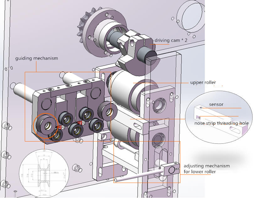
2. Nose strip insetting and embossing station
Before analysis to this station, one question should be answered is why a layer of material is processed at the top. As we all know, N95 mask is not disposable mask whose nose strip is inset by folding the single layer of material. Therefore, the outermost material should be processed at the top so that nose strip can be inset between the material layers.
1) Flow order
a. The outermost material and other material are fed into the station in the path shown in the above figure;
b. While material is being conveyed into the station, the nose strip insetting station will inset the strip between cloth layers.
2) Mechanisms
a. Material transferring device
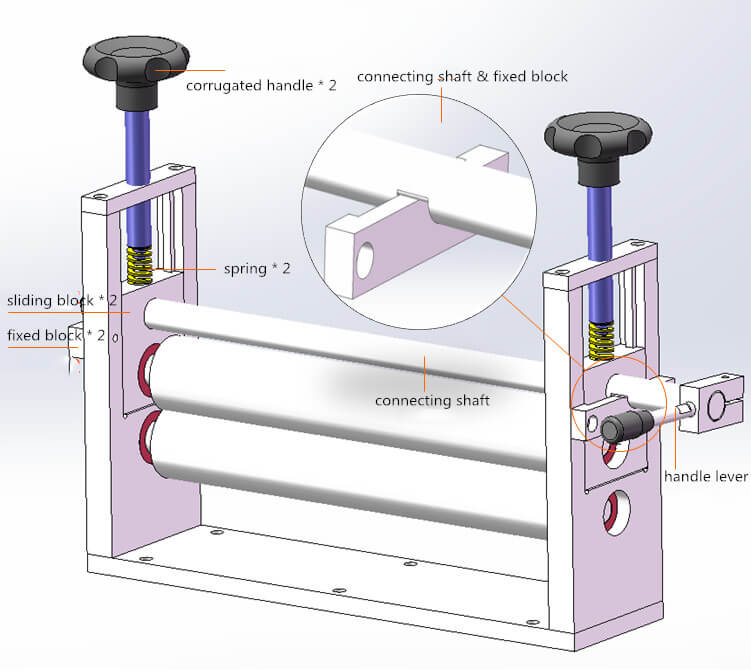
This device can press material layers. The principle is: tightening the corrugated handle and then compacting sliding block with springs.
The function of this device is pretty simple, so let’s us discuss its features directly. It can be found the fixed block is stuck into a groove of connecting shaft. In this case, the connecting shaft will also lift or lower as it rotates. When hand lever is rotated, the upper roller will lift. Therefore, new material can be placed between the two rollers conveniently.
b. Nose strip feeding and insetting mechanism
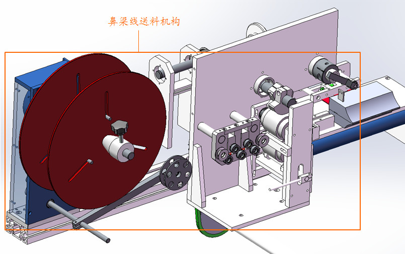
Nose strip feeding mechanism
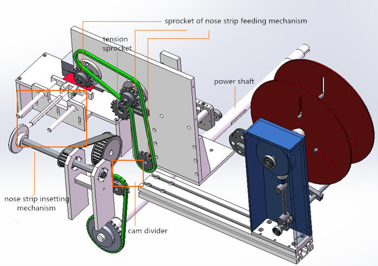
a) Driving of this mechanism
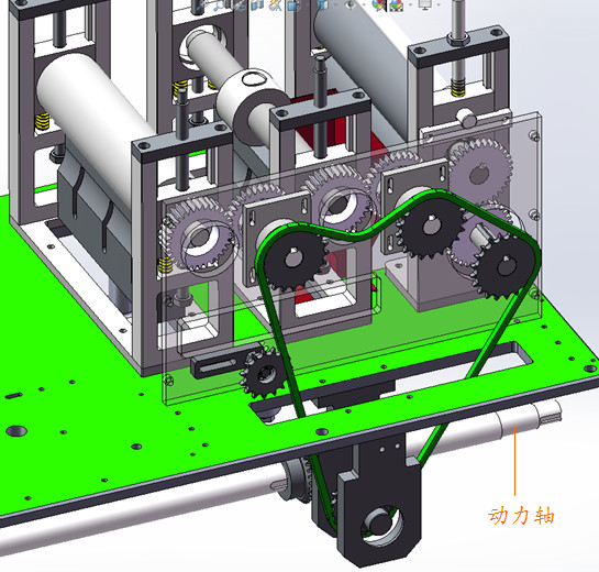
This mechanism is totally driven by the power shaft, which also provides power for the following stations.
Afterwards, powers is transferred to cam divider and at last to nose strip feeding and insetting mechanisms.
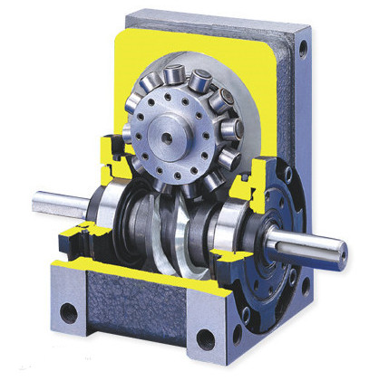
How is cam divider like?
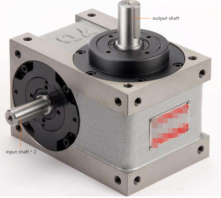
There are two input shaft and one output shaft. The input shafts connect with power and material feeding sprocket and the output shaft with synchronous wheel of material insetting mechanism.
From the above figure, the two input shafts is an integration so that power can be directly delivered to material feeding sprocket which moves without intermission. On the other hand, the synchronous wheel connecting with output shaft becomes to rotate intermittently due to inner structure of divider.
b) Nose strip feeding mechanism
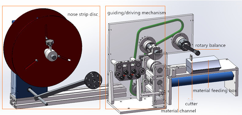
i. Flow order
Material disc → guiding/driving mechanism. (Material disc needn’t power to drive and nose strip is driven by driving mechanism.)
Guiding/driving mechanism → material channel → material feeding box.
After nose strip is fed, rotary balance drives cutter to cut the strip and then insetting mechanism pushes the strip into cloth materials.
The above process repeats.
ii. Working principle
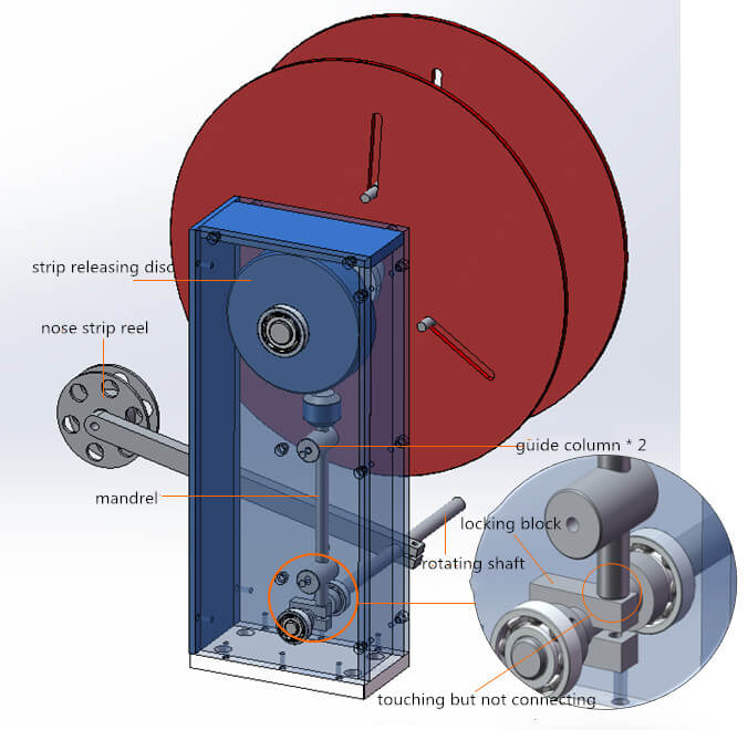
Nose strip reel → rotating shaft → locking block → mandrel → strip releasing disc
This mechanism can feed strip when there lacks material at guiding/driving mechanism, while stops when too much material is released. Particular working principle can be explained as:
Nose strip is conveyed under strip reel. When material lacks at guiding/driving mechanism, the nose strip will be tensed so that strip reel is lifted and drives rotation of rotating shaft. The shaft then drives locking block to move clockwise and lowers down mandrel. Afterwards, material disc rotates.
On the other hand, nose strip will be loose if it is over-released. Therefore, strip reel moves down and the following movements are opposite to the above process. At last, mandrel support material disc and stops its motion.
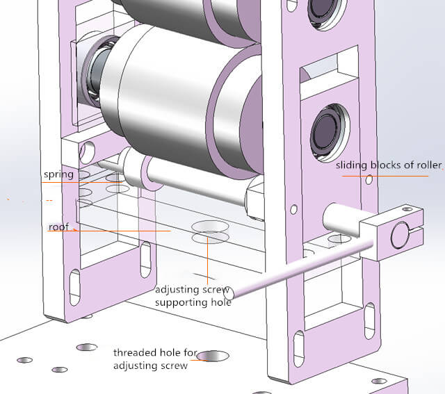
The adjusting mechanism for lower roller works in the same principle and for the same function with the material transferring mechanism. What differs between them is that the adjusting screw firstly support the roof which then support the roller through the spring between it and roller’s sliding block.
Function of guiding mechanism is to avoid strip deviation. We can see from the picture that the two rollers at the left and right are V type, which can prevent nose strip from deviating to two sides.
After guiding mechanism, nose strip is conveyed through sensor installation block, between rollers then and to the material channel at last. The driving cam drives rollers. As it rotates one circle, it touch the roller once and drives the rollers’ rotation.
You might also ask why two cams are needed? Actually, two cams can help the users to adjust their contacting angles with rollers conveniently so as to adjust releasing length of nose strip conveniently.
c) Nose strip insetting mechanism
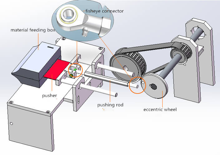
This mechanism moves in the order: eccentric wheel drives pushing rod and pusher forwards to inset nose strip between material.
c. Embossing mechanism
Power shaft
Power of this mechanism also comes from power shaft, which the one provides shaft for nose strip feeding and insetting mechanism.
The following picture shows details of this mechanism:
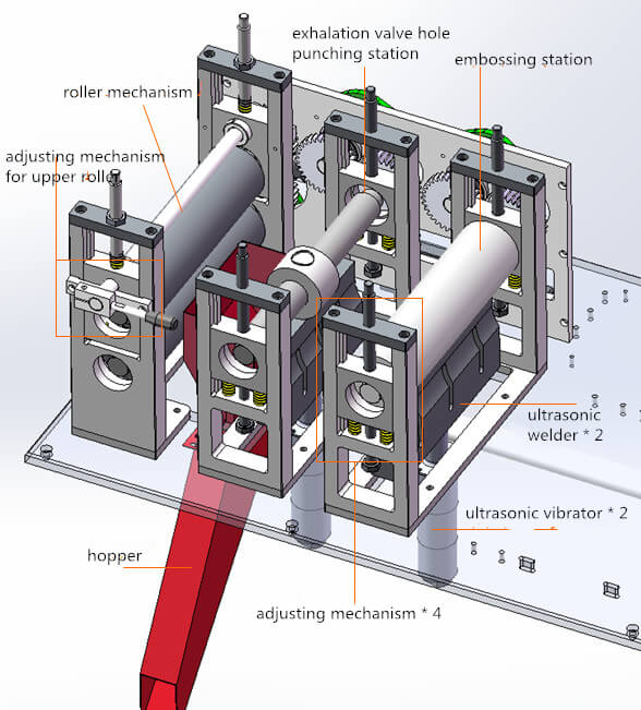
a) Embossing station
There are lines on its rollers (not shown on the picture) to emboss the veins on N95 mask.
The adjusting mechanism of this station is also clear. The upper and lower screws can fix the sliding block. The central spring functions to lift embossing roller when the upper screw is loosened without fastening the lower screw.
b) Exhalation valve hole punching station
A protruding circle of roller can punch holes for exhalation valve. The punched waste is discharged through hopper. But the mask produced on this machine has no exhalation valve, so this punching station is not necessary.
c) Roller mechanism
It can drive cloth material forwards.

 English


